Optimising Bluetooth device battery drain measurements in manufacturing
Ref: z2511083m
(Information provided by Concilium Technologies, 012 678 9200, [email protected] )
Battery operating time is a critical parameter for portable devices. It is a key factor that consumers weigh heavily in their purchasing decision. Reducing battery drain to improve operating time is a top priority for early Bluetooth designs. To assure meeting specified operating time, the manufacturing test engineer must select appropriate Bluetooth operating states for making battery drain measurements while still meeting tight cost and throughput goals. In addition, the wide range of levels and the pulsed nature of the battery drain for Bluetooth devices dictate using specialised test equipment for optimum test accuracy, throughput, and lowest cost in manufacturing.
Key representative operating states for manufacturing test
Bluetooth devices feature many operating states, each providing a certain capability with a corresponding power drain. This enhances performance as a networked device, while still optimising battery-operating time. Key representative operating states need to be identified for making battery drain measurements to assure specified operating time while minimizing testing. Due to the wide potential diversity of Bluetooth applications, key operating states will depend largely on the intended application of the particular device and its dynamic range of operation, making their identification challenging. Most key operating states fall into four broad categories, including battery charging for rechargeable devices.
These categories are:
1.Active call state operation.
2.Standby/scan state operation.
3.Low power modes of operation.
4.Battery charging (when applicable).
Active call state operation
The highest level of power drain is when the Bluetooth device is linked and actively communicating with the host network. A large portion of the power is drawn by the respective Bluetooth RF and baseband circuitry. Its power consumption will depend on transmit power and rate. For example, power class 1 devices output up to 100 mW (20 dBm), having a range of up to 100 m. At the low-end, power class 3 devices output only up to 1 mW (0 dBm) of RF power for close proximity operation. Regarding rate, a headset is an example of a device that transmits at a continuous rate with a corresponding continuous high power drain. In comparison, a room thermostat may transmit for only a few milliseconds, once every minute, using much less power.
A second potentially large portion of the power is unique to the function of the particular device, which is over and above the Bluetooth RF and baseband circuitry. One higher power example is an illuminated colour display, which can consume up to several watts of power.
Bluetooth is a digital time multiplexed transmission format. As a result most battery-powered Bluetooth devices in active call state operation typically draw pulsed current with the following characteristics:
* Average and high level current from tens of milliamps up to amps.
* A low-level current from milliamps up to hundreds of milliamps.
* Crest factors on the order of 10X.
* Waveform periods with multiples of the 1,25 ms frame rate.
Primary measurements for the active call state current drain in manufacturing test include:
* The DC current as it is the most fundamental measurement verifying battery operating time.
* Peak and high-level currents as they can cause excess battery voltage droop and are an indicator of device faults.
Measurement system needs for performing such measurements include:
* Ability to handle high crest factor signals.
* Accuracy of 0,5% or better for the DC level of interest.
* Adjustable integration time for fast and accurate averaging over waveform periods.
* Ability to track and capture maximum and high level waveform values.
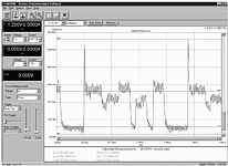
These characteristics and their measurement needs pose challenges to most test equipment. Most system DC sources have very basic measurement capabilities and are usually not adequate for pulsed load currents. Most DMMs do not have the necessary integration time control, which is the key to accurate measurement with good throughput. Likewise, most general-purpose equipment does not have the ability to capture peak and maximum values of the active call state current. Figure 1 illustrates an actual current drain waveform measurement taken on a Bluetooth headset device operating in an active call state.

Standby/scan state operation
Acting as a slave device
When not networked, a Bluetooth device acting as a slave will be operating in standby, at an intermediate to low power level. During each scan period the device wakes up to receive and check for pages and/or inquiries. This produces a pulsed current drain with the following typical characteristics:
* One or two 11,25 ms pulses within a 1,28 second scan period.
* High levels from tens to hundreds of milliamps.
* DC levels from single to tens of milliamps.
* Low levels from tens of microamps to tens of milliamps.
* Crest factors from 10 to 1000X.
Next to active call, standby/scan state DC current drain is the second most common measurement made in manufacturing to assure meeting the specified battery operating time of the device. Long standby time is a critical end-user requirement.
The measurement system needs for standby/scan state include:
* Ability to handle very high crest factors.
* Accuracy of 0,5% or better for average levels from single to tens of milliamps.
* A settable integration time for accurate averaging over long (>1 s) waveform periods.
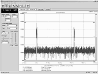
Figure 2 illustrates the current drain of the example Bluetooth headset device in the standby/scan state. Standby/scan state measurements are even more challenging than active call state due to the lower current levels and long signal period. As a result most general-purpose test equipment and system DC sources do not adequately address these measurement needs for optimum test throughput and accuracy.

Acting as a master device
Conversely, a Bluetooth device acting as a master during the standby/scan period transmits a series of pages or inquiries in an effort to contact a slave device. For this situation the device's current drain characteristics and measurement needs are basically the same as that for the active call state operation.
Low power modes of operation
During periods of inactivity the Bluetooth device can be placed into low power modes of operation, such as PARK, HOLD, and SNIFF, for extended time periods to conserve power. During these periods the device enters into sleep mode drawing as little as only tens to hundreds of microamps of current.
To further conserve power many Bluetooth devices can be placed in off-mode, where they likewise draw as little as only tens to hundreds of microamps of current. The example Bluetooth headset device was found to draw 121 µA of current in its off-mode.
There is very high value in testing current drain to assure against unexpectedly high battery drain in these low power modes as well as identifying existing and latent manufacturing defects in the device.
Key measurement system needs include:
* A low-level current measurement range of about 10 mA.
* 10 µA or better measurement accuracy.
* A suitable measurement delay and integration time for obtaining a stable reading.
Most system DC sources do not adequately address the measurement needs for low power modes of operation, not having sufficient accuracy for making microamp level measurements.
Battery charging mode of operation
For higher power Bluetooth devices incorporating rechargeable batteries, the charging function will be typically built in. For proper charging function, the battery charge current and voltage needs to be measured and calibrated as part of the manufacturing test process.
Key measurement system needs include:
* Able to measure the charge current (typically up to 1 A) with 0,5% or better accuracy.
* Able to measure the charge voltage (typically up to 9 V) with 0,2% or better accuracy.
Additional system needs include:
* The DC source should double as a constant voltage load and sink the charging current to emulate a charging battery.
* A second DC source is needed to provide the charging current.
Most general-purpose DC sources do not have the necessary features to support the battery-charging mode of operation for test and calibration during manufacturing test, not able to operate as a constant voltage load and sink the full level of charging current.
Optimising throughput and accuracy with minimum measurement integration time
Controlling the measurement integration time is necessary for measuring the DC values of the pulsed current drains for Bluetooth active call and standby/scan states. Being able to precisely set the integration time optimises test throughput and accuracy.

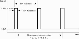
A pulsed current drain example is shown in Figure 3. When the measurement integration time is precisely set to an integral multiple of the pulse period, the measurement accuracy is predominantly the specified DC accuracy of the test equipment. However, when there is even a small mismatch between the pulse period and integration time, significant error is encountered. This mismatch usually manifests itself as repeatability error and it occurs when either a part of a pulse is missed or an additional part of another pulse is captured in the integration. The objective is to make this mismatch error a small part of the overall error budget.
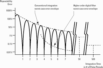
As an example, using an integration time that is 10% too long, 4,13 ms instead of 3,75 ms, on the signal in Figure 3 will produce about 45% error when a second pulse is captured. The error decreases with longer integration time and number of pulses averaged. A 10-fold longer integration time will have one-tenth the error. The accuracy is improved at the expense of reduced test system throughput. This relationship is summarised in figure 4.

The integration time for a typical DMM is set in power line cycles (PLCs). A PLC is 16,7 ms for 60 Hz and 20 ms for 50 Hz. Using PLCs minimises AC line interference error. However, the limited integration time adjustment of a typical DMM, based on PLCs, is not well suited for measuring nonPLC-based pulsed currents. This leads to seconds-long integration time, over hundreds of pulse periods, in order to make the mismatch error a small part of the overall error budget. Making several measurements in active and standby/scan states with a general purpose DMM can add tens of seconds to the test time. Specialized test equipment providing the necessary integration time accuracy and resolution minimises measurement time, optimising test throughput and accuracy.
Digital filtering as an alternate approach for optimising measurement throughput and accuracy
With sampling measurement systems, digital filter signal processing can be used to significant advantage, as an alternative to conventional measurement integration. By applying weighting factors to the sampled values from the acquisition, very low repeatability error is achieved in a small number of pulse periods, thus providing high throughput and accuracy for DC measurements. The order and shape of the digital filter function determine what the weighting factors are. An example of a higher order digital filtering worstcase error envelope is shown by the lower curve in Figure 4. In this case the repeatability error becomes negligible within six pulse periods. Being the envelope, the low level of error is achieved independent of exact matching of the pulse period. This is a major advantage when the pulse period is not precisely known or controlled, as well as when there is another signal to reject, such as AC line frequency interference. Some specialised sampling measurement test equipment provide such capabilities as standard.
Summary
Accurate DC current measurements for battery powered Bluetooth devices are fundamental in assuring specified battery operating time, calibration, and quality. Table 1 summarises these key test parameters and system measurement needs. In optimising manufacturing test it is important for the test engineer to appropriately select these key operating states to best assure the specified battery operating time is met while still minimising the amount of testing.
The wide range of levels and pulsed characteristics for Bluetooth device current drains are a challenge to measure in manufacturing. These measurement needs are not adequately addressed by general-purpose system DC sources and measurement equipment. Specialised test equipment providing measurement ranging and pulse signal integration are key to optimising test accuracy, throughput, and cost.
The Agilent 66319B/D and 66321B/D DC sources are ideal solutions for manufacturing test of battery-powered Bluetooth devices. They incorporate a specialised high-speed sampling measurement system with digital signal processing to address test needs specifically for such digital devices drawing pulsed current. Due to this advanced measurement system these DC sources provide both accuracy and throughput for optimum test results, at a low cost.

Key features include:
* Current ranging for high accuracy measurement from amps, down to microamp levels, for testing high and low power modes of operation.
* High-speed sampling digitises pulsed current waveform and its parameters, including peak and high levels, for active call state testing, to guard against premature low battery shutdown.
* 15,6 µs integration time resolution for fast and accurate conventional integrating measurements of pulsed currents, for optimising test throughput.
* Alternate DSP-based digital filtering setting for fast and accurate DC measurement of pulse currents, independent of exact period, for optimising test throughput.
* CV load operation (current sinking) for testing and calibrating battery-charging circuits.
* Second output available for replacing battery charger during test.
(Information provided by Concilium Technologies, 012 678 9200, [email protected])

© Technews Publishing (Pty) Ltd | All Rights Reserved