
The IXDP610 integrated circuit is a digital pulse width modulator (DPWM) from Ixys that is targeted for microcontroller and microprocessor based systems used for switching power bridge applications, PWM controlled current or voltage sources, and other switching based designs. A programmable CMOS device, it accepts digital pulse width data from a microcontroller and generates two non-overlapping, pulse width modulated signals for direct digital control of switching bridges. From correct understanding of the basic PWM concepts, proper hardware design can be implemented and then the IXDP610 configuration can be specified.
Discussion
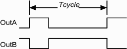
The IXDP610 is designed to generate complementary square wave output waveforms for pulse width modulation (PWM) applications. The concepts of PWM cycle time, pulse 'ON' time (also called duty cycle), duty cycle resolution and programmable dead time are key. When designing a PWM waveform one of the first parameters to define is the PWM cycle time. The PWM cycle time is the interval between successive pulses. It is the inverse of the PWM frequency. For applications using the IXDP610 this parameter is important since it is dependent upon the input clock frequency. The PWM cycle time should be the main consideration when selecting the external clock frequency. The IXDP610 is capable of operating in 7-bit or 8-bit resolution. In 7-bit resolution the PWM cycle time is 128 counts of the input clock. In 8-bit resolution the PWM cycle time is 256 counts of the input clock. This leads to the following relationships: (Figure 1 shows a graphical representation of the PWM cycle time.)
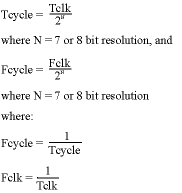
The final variable within the IXDP610 to modify the PWM cycle time is the DIV bit in the IXDP610 control register. It is bit 5 in the control register and it enables a divide by two of the input clock. Here is the revised PWM cycle equation - factoring in the effect of the DIV bit being set:
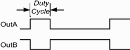
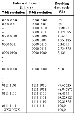
Once the PWM cycle time is defined, it is necessary to specify the PWM pulse width register to set the 'ON' time. This parameter, also called the duty cycle, defines when the noninverted output is logic high, or 'ON'. Conversely, it defines when the inverting output is logic low or 'OFF'. It is configurable from a value of 0 to 2N where N = 7- or 8-bit resolution. When the pulse width register is programmed with a 0 or a 1 the noninverting output will be a DC logic low and the inverting output will be a DC logic high. When programmed with 2N-1 where N = 7- or 8-bit resolution the noninverting output will be a DC logic high and the inverting output will be a DC logic low. These two states can be used for braking or DC operation depending upon the user-specific hardware after the IXDP610. When the pulse width register is programmed with any value from 2 to 2N-2, a switching waveform with a duty cycle that follows this relationship will result:
where
N = 7 or 8 bit resolution and PW is any count value from 2 to 2N-1 See Figure 2 and Table 1 for additional representations of the PWM duty cycle.)
From Table 1 the concept of duty cycle resolution or pulse 'ON' resolution can be understood. The duty cycle resolution is the minimum discrete step the IXDP610 can make between possible duty cycles. In 7-bit resolution the minimum step is 1,5625%. In 8-bit resolution the minimum step is half of that or 0,78125%. This is the discrete accuracy of an IXDP610 implementation. It will correlate to the minimum control step size of the device being controlled (ie speed of a motor, volts or amps of a switching source, etc).
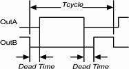
The final parameter that defines the IXDP610 PWM output waveform is the dead time. Since transistors do not have instantaneous turn-off, there is potential for a short circuit current to pass between the two transistors used in a half bridge configuration. To prevent this condition the IXDP610 has the ability to create two non-overlapping signals. The dead time is the time between the two outputs asserting logic high. In a PWM waveform with no dead time allotted, when the noninverting output goes low, the inverting output transitions high at the same time. (And the inverse is true, when the inverting output goes low and the noninverting output goes high at the same time.) The dead time count can be set from 000b to 111b. This allows for eight possible dead times. Each bit in this count represents two clock cycles, therefore the dead time can be set from 0 to 14 clock periods. In typical PWM cycles that are switching, there are two dead times as illustrated in Figure 3. The first is when the noninverting output goes from low to high. This is concurrent with the inverting output transitioning from high to low. During this dead time period the noninverting signal is delayed by the dead time count, and the ON time is shortened by the dead time. The second dead time occurs when the inverting output transitions from high to low and the noninverting signal transitions from low to high. Again the signal going high is shortened by the dead time.
Conclusion
The concepts of PWM cycle time, dead time, duty cycle, and duty cycle resolution create the IXDP610 output waveform. Understanding their interdependence is the key to creating a successful hardware design and software configuration when using the IXDP610. When designing with the IXDP610 the most critical hardware design choice involves the external clock frequency. The external clock directly defines the PWM cycle time, duty cycle resolution and dead time intervals. The configurable nature of the IXDP610 duty cycle allows the end user the opportunity for precision control, low power states, brake states, and DC operation. The additional feature of dead time control improves efficiency by eliminating potential short circuit currents in the power transistors used in switch mode architectures. With all of these options in one device it becomes an essential tool for any design that requires the precision of digital control with power electronics used in switching architectures.
For more information: Avnet Kopp, 011 809 6100, [email protected]

© Technews Publishing (Pty) Ltd | All Rights Reserved