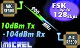

The MICRF500 from Micrel is a single chip UHF transmitter and receiver intended for ISM (industrial, scientific and medical) and SRD (short range device) frequency bands from 808 MHz to 915 MHz with FSK data rates up to 128 k baud. It can also be programmed for operation at other frequency bands in the 700 MHz to 1000 MHz range.
The transmitter consists of a PLL frequency synthesiser and a power amplifier. The frequency synthesiser consists of a voltage-controlled oscillator (VCO), a crystal oscillator, dual-modulus prescaler, programmable frequency dividers and a phase-detector. The loop filter is external for flexibility and can be a simple passive circuit. The VCO is a Colpitts oscillator which requires an external resonator and varactor. FSK modulation can be applied externally to the VCO. The synthesiser has two different N, M and A frequency dividers. FSK modulation can also be implemented by switching between these dividers (max. 2400 bps). The lengths of the N and M and A registers are 12, 10 and 6 bits respectively. The output power of the power amplifier can be programmed to eight levels. A lock detect circuit will detect when PLL is in lock.
In receive mode the PLL synthesiser generates the local oscillator (LO) signal. The N, M and A values that give the LO frequency are stored in three registers. The receiver is a zero IF (intermediate frequency) type in order to make channel filtering possible with low-power integrated low-pass filters. It consists of a low noise amplifier (LNA) that drives a quadrature mixer pair whose outputs feed two identical signal channels in phase quadrature. Each channel includes a preamplifier, a third order Sallen-Key RC low pass filter that protects the following gyrator filter from strong adjacent channel signals and finally, a limiter.
The main channel filter is a gyrator capacitor implementation of a seven-pole elliptic low pass filter. This filter minimises the total capacitance required for a given selectivity and dynamic range. The cut-off frequency of the RC filter can be programmed to four different frequencies: 10 kHz, 30 kHz, 60 kHz and 200 kHz. An external resistor adjusts the cut-off frequency of the gyrator filter. The demodulator demodulates the I and Q channel outputs and produces a digital data output. It detects the relative phase of the I and the Q channel signal. If the I channel signal lags the Q channel, the FSK tone frequency lies above the LO frequency (data '1'). If the I channel leads the Q channel, the FSK tone lies below the LO frequency (data '0'). There is an RSSI (receive signal strength indicator) circuit that indicates the received signal level. A two pin serial interface is used to program the circuit.
External components are necessary for RF input and output impedance matching and decoupling of power. Other external components are the VCO resonator circuit with varactor, crystal, feedback capacitors and components for FSK modulation with the VCO, loop filter, bias resistors for the power amplifier and gyrator filters. A T/R switch can be implemented with 2-pin diodes. This gives maximum input sensitivity and transmit output power.
The MICRF500's RF output power is 10 dBm, sensitivity is -104 dBm (19,2 k bauds, BER=10-3) and max data rate is 128 k bauds. Applications are found in: telemetry; remote metering; wireless controller; wireless data repeaters; remote control systems; wireless modem; wireless security system. MICRF500BLQ comes in 44-lead LQFP.
| Tel: | +27 11 728 4757 |
| Email: | [email protected] |
| www: | www.mbsiliconsystems.co.za |
| Articles: | More information and articles about MB Silicon Systems |

© Technews Publishing (Pty) Ltd | All Rights Reserved