



Accurately measuring the electromagnetic field (EMF) is essential to confirm that exposure levels comply with the regulatory limits established in each country, and thus ensure the safety of individuals exposed, whether members of the general public or workers.
How to measure exposure to electromagnetic fields
Exposure to electromagnetic fields is generally measured using a probe and a receiver (voltmeter or power meter). An electromagnetic field probe is an ‘antenna’ that has been optimised to measure exposure to electromagnetic fields.
There are two types of probes used for measuring exposure to electromagnetic fields: broadband probes and frequency selective probes. A broadband probe is generally composed of a set of diodes and dipoles. Each diode is connected directly between the two poles of a dipole. Using this type of probe, the voltage proportional to the field level is measured. The quality of this type of probe will therefore depend on its ability to provide the same voltage for the same field and regardless of the frequency (frequency is of course within the usage bandwidth) of the field to be measured.
These broadband probes provide information on the level of exposure, but do not indicate the frequency of the field to which the user is exposed. They are mostly used in warning products (personal protection monitor, or PPM) or for a quick measurement of compliance when measured levels remain low. This type of probe is defined by its isotropy, its bandwidth, its sensitivity, its measurement dynamic, its frequency flatness and its linearity.
The second type of probe, depending on its receiver topology, provides information regarding the frequency and the amplitude of the measured field, as well as information on the level. They are incorporated into more refined compliance or information measuring products. They are defined by their isotropy, their bandwidth, and their antenna gain or factor; the dynamic sensitivity and linearity in this case are dependent on the receiver topology used with a given probe.
Personal protection from EMF, even at 5G frequencies
Occupational safety for those exposed to higher levels of EMF during their working day has long been a major consideration for sectors such as telecommunications, defence and aerospace. Even more so since the mainstream introduction of 5G bandwidths.

Protecting those working with microwaves, radar frequencies and 5G millimetre waves with PPM which is reliable, convenient and effective is vital in satisfying occupational safety requirements of these industries. From persons responsible for the installation and maintenance of antennas, to broadcast, PMR and mobile phone operators or those visiting sites for regulatory purposes, fully tested PPM must be issued and the user trained in its use to ensure complete safety in the workplace.
To solve this complex monitoring challenge, and to accommodate the now common 5G frequencies, Microwave Vision Group (MVG) has introduced to market the EME Guard XS 40 GHz, an EMF monitoring device to alert and protect workers near antennas.
Continuous, accurate, personal protection
Worn with a wrist strap, lanyard or arm strap, the EME Guard XS 40 GHz offers substantial frequency coverage from 1 MHz up to 40 GHz and continually monitors electromagnetic fields, using isotropic tri-axis E-field sensors, no matter how the device is orientated for wear.
The EMF level is displayed by a clear colour scale on the front of the device. Featuring seven LED lights which climb from green to red according to RF exposure, the instrument beeps audibly at key points along the scale to alert workers to the increasing dangers of their environment. By alerting device wearers with audible sounds to attract attention, workers can check the visual display and perform the relevant risk assessments in accordance with company and industry legislation for working standards.
The display scale has been designed in a way that helps workers to decide in split seconds how much longer they can safely continue working in that area, or whether immediate evacuation is required.
Automatic compliance with standards
MVG has intentionally designed the EME Guard XS 40 GHz LED and audible beep alert system to be simple to read and easy to interpret, so that workers can operate in a standards-compliant way. Alarm thresholds can be adjusted at the MVG factory to suit the geographical location of any workforce and the permissible limits set by each associated governing body.
By tailoring devices in this way, workers can perform their duties in a way which is automatically compliant with EU Directive 2013/35/UE, ICNIRP 2020, FCC 96-326, or Safety Code 6 2015, without having to interpret EMF readings in the field in accordance with their own standards. This reduces the risk of human error, making operation safer, and any potential evacuation or leak detection faster.
Leak detection and personal protection in one device
By removing the EME Guard XS 40 GHz from your preferred wearable position, it can be used as a handheld leak detection device when checking specific areas for leaks, such as around an equipment room or coax cables, plus along the single point ground area and out to the antenna side. Having fast access to a leak detection device improves occupational safety on site, empowering workers to react to potential hazards in a more efficient fashion.
Simple maintenance, maximum performance
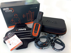
The EME Guard XS 40 GHz has an automatic integrated self-test function which activates every time the device is switched on, autonomously checking the functionality of the LED lights and audible sounds for any potential faults. The device requires two 1,5 V, size N alkaline batteries, which deliver more than 1000 hours (50 days) of performance if no alarm is triggered. Maintaining optimal performance in accordance with occupational safety guidelines, each EME Guard XS 40 GHz requires verification every two years.
More from the EME Guard family
For other highly specific personal monitoring and protection, the EME Guard family offers a range of highly accurate and easy-to-use products:
The EME Guard XS provides accurate measurement with tri-axis sensors and it monitors the frequency bands from 80 MHz to 6 GHz.
The EME Guard XS Radar has been specifically designed to alert workers of their safety parameters when working close to radar transmitters. It measures from 80 MHz up to 30 GHz and it allows detection of short pulsed signals.
The EME Guard is designed for workers who work close to emitting antennas such as broadcast, base station and radars. EME Guard not only monitors EMF in the 27 MHz to 40 GHz range, but also allows data storage and customisation of vibrating as well as audible and visual alarms.
How to measure exposure to electromagnetic fields
Isotropy
The isotropy characterises the ability of the field measuring probe to always provide the same response to a given field level, regardless of the direction of arrival of this field or its polarisations. It is a parameter required by most of the current measurement standards. There is no single naturally isotropic antenna; for electromagnetic field probes, this isotropy is thus obtained by combining the radiation pattern of three elementary antennas (dipole or monopole) appropriately placed with respect to each other.
Bandwidth
The performance of an electromagnetic field measurement probe varies according to the frequency of the field to be measured. They are thus defined to be used over a limited frequency range, known as the usage bandwidth.
Sensitivity
The sensitivity of an electromagnetic field measurement probe or system is the minimum level of the field that can be measured with this tool.
Dynamic range
The dynamic range of an electromagnetic field measurement probe or system is the difference between the maximum and minimum field that can be measured with this tool. It is generally expressed in dB.
Frequency flatness
This parameter characterises the quality of a broadband probe. It represents the variations of the measured E-field at a fixed frequency, when the level of the E-field is varied over the dynamic range of the probe.
Linearity
This parameter characterises the quality of a broadband probe. It represents the variations in the levels measured, with fixed frequency and making the level of the field measured over the probe’s measuring range vary.
Antenna gain and/or factor
Antenna gain (respectively of an electromagnetic field measuring probe) characterises its ability to emit (respectively receive) in a specified direction. It is generally expressed in dBi, taking as a reference an isotropic antenna, meaning a fictitious antenna that radiates uniformly in all directions. The gain of this antenna is thus 1, or 0 dBi (dBi stands for decibel-isotropic).
The role of an electromagnetic field probe is to transform the received electromagnetic field level into RF power. The antenna factor is defined as the ratio of the electromagnetic field captured by this antenna to the voltage measured at the antenna terminals.
The antenna factor (expressed in dB) is linked to its gain by the following equation: AF = 20 x Log(F) - G - 29,78. In this equation, F is the frequency in MHz, and G is the gain in dBi. AF is also equal to E/Vr.
The power received by an antenna capturing an electromagnetic field can easily be found using the following formula: Pr = 20 x Log(E) - AF + 13. In this equation, Pr is expressed in dBm, E in V/m and the antenna factor in dB.
| Tel: | +27 87 265 2544 |
| Email: | info@conical.co.za |
| www: | www.conical.co.za |
| Articles: | More information and articles about Conical Technologies |






© Technews Publishing (Pty) Ltd | All Rights Reserved
 printer friendly version