


Standby battery backup systems play a critical role in keeping essential operations functional in the event of a utility outage. Facilities like data centres, hospitals, airports, utilities, oil and gas facilities, and railways cannot operate without 100% backup power reliability. Even standard commercial and manufacturing facilities have backup power systems for their emergency systems, alarms and controls, emergency lighting, steam and fire control systems.
Most backup power systems use an uninterruptable power supply (UPS) and a string of batteries. The UPS backs up the digital control system to keep control of plant operations until systems can be safely shut down or until the auxiliary generator starts to supply power.
Although most batteries used in modern UPS systems are “maintenance free”, they are still susceptible to deterioration from corrosion, internal shorts, sulphation, dry-out, and seal failure. Best practices can be outlined for assessing whether battery banks are maintaining optimum performance, to ensure that the backup is ready if an outage occurs.
The top two indicators of battery health are internal battery resistance and discharge testing.
Internal resistance is a life-span test, not a capacity test. Battery resistance stays relatively flat up until the end of life draws near. At that point, internal resistance increases and battery capacity decreases. Measuring and tracking this value helps identify when a battery needs replacing.
A specialised battery tester designed to measure battery resistance is necessary for this measurement while the battery is in service. Either the voltage drop on the load current (conductance) or the AC impedance will indicate the battery’s internal resistance. However, a single ohmic measurement is of little value without context. Best practice requires measuring ohmic values over months and years, each time comparing them to previous values on record to create a base line.
Discharge testing is the ultimate way to discover the true available capacity of a battery but can be complicated to perform. In discharge testing, a battery is connected to a load and discharged over a specified period. During this test period, current is regulated, and a constant known current is drawn while voltage is measured periodically. Details of the discharge current, the specified period for discharge testing, and the capacity of the battery in ampere-hours can be calculated and compared to the manufacturers’ specification. For example, a 12 V 100 Ah battery may require a discharge current of 12 A for an eight-hour period. A 12 V battery would be discharged when the terminal voltage is 10,5 V.
Batteries cannot support critical loads during and immediately after a discharge test and all critical loads should be transferred to a different battery bank until well after the test is completed. In addition, before conducting the test, a cooling system to compensate for a rise in ambient temperature should be prepared as large batteries release a significant amount of energy when discharging.
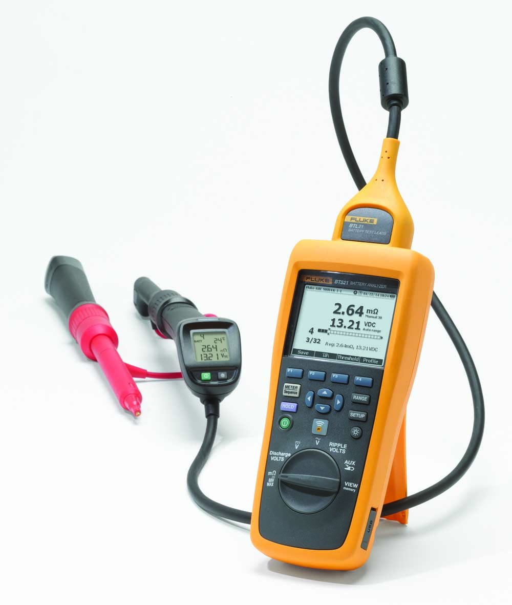
A Fluke 500 Series Battery Analyser is able to provide a new level of ease-of-use in battery testing and is the ideal tool for maintenance, troubleshooting and performance testing of individual stationary batteries and battery banks used in critical back-up applications.


© Technews Publishing (Pty) Ltd | All Rights Reserved
 printer friendly version