


Engineers are striving to achieve 100% failsafe systems; however this Utopia is very difficult to realise in practical implementations and in a cost-effective way. Therefore a probabilistic and risk-based approach is normally adopted to define the level of functional safety required for safety relevant systems, as in standards like ISO 26262 and IEC 61508.
These standards define the (Automotive) Safety Integrity Levels (ASIL/SIL) which specify which attributes of a system have to be observed and the degree of rigour of the engineering process that must be applied to achieve the related certification of a system.
This includes a safety concept defining the safety goals of the system and the tolerable error rate, followed by a safety architecture which distributes the functions into hardware and software functionality that permanently detects that the system is running correctly.
Traditionally the safety software, hardware and tools were only island solutions, solving parts of the requirements but in a disjointed way. Infineon has now developed the integrated PRO-SIL concept which offers a complete solution to achieve functional safety in an efficient and integrated manner to minimise risk, save cost and reduce complexity.
The fundamental motivation for the development of ‘safe’ systems is to ensure a safe operation and defined behaviour in the event of defects. Against this background, the IEC 61508 standard was developed in the mid-1980s, and since then repeatedly revised.
This standard defines the design of safe systems for electrical and electronic devices. Furthermore, derivatives of this general standard have been developed for the specific demands of process automation (IEC 61511), machinery automation (ISO 13849), drives (IEC 61800-5), nuclear (IEC 61513) and automotive (ISO 26262 draft).
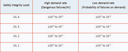
The measures to ensure IEC 61508 compliance depend upon the required Safety Integrity Level (Table 1) for each hazard in the system (SIL 1 up to SIL 4 for automation applications and ASIL A to ASIL D for automotive applications).
In the last couple of years, functional safety has moved from a system integrator’s task to the component/software level. Simple electronic components as well as complex microcontrollers have to support IEC 61508. One of the most important and often time-consuming challenges for system designers is the requirement to ensure the safety of systems and get the related certifications not only at the top level but also deep down in the hardware and registers of the machine.
The IEC 61508 prescribes detailed requirements for hardware supervision and testing, which by its very nature is very hardware specific. Writing safety critical software to perform these functions is therefore time consuming and expensive, and is not easily portable between devices.
Multiple CPUs – cost and space intensive
With a single-channel architecture using one microcontroller, the maximum safety integrity level was limited to SIL 2. Therefore SIL 3 or ASIL C/D systems and safety products were designed using multiple CPUs, to take care of the self-testing and ensure redundancy. But this is a complex and costly solution with a large PCB footprint and coverage limited by synchronisation and communication issues between the two CPUs.
A new approach is to go beyond the limits of the stated medium diagnostic coverage (DC) by adding special external hardware blocks and using a software library running on a standard dual-core 32-bit microcontroller. This solution makes the inclusion of safety in a related system fast and reliable by reducing development effort and material costs to only one microcontroller, and using an intelligent safety concept with all related components including ready-to-use self-test functions developed according to IEC61508/ISO26262.
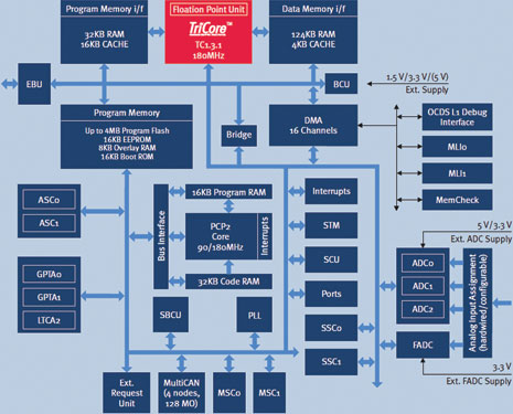
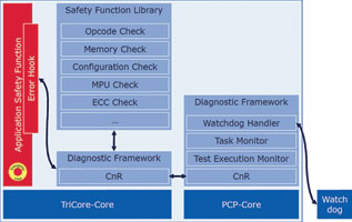
Instead of using a second external core to evaluate functional failures of the microcontroller, Infineon’s TriCore already includes two cores (Figure 1) – the TriCore CPU itself (microcontroller and DSP) and the Peripheral Control Processor (PCP) – making the external second core for safety evaluation obsolete.
Complete design package
There are already different solutions on the market to implement safety critical applications. While most leading vendors offer related approaches for automotive applications, the applicability to other application areas including industrial is constrained and the available device roadmaps are often limited.
Leveraging its experience with stringent safety requirements of automotive systems, Infineon has developed its PRO-SIL range of safety products to address the increasing needs of the industrial market with highly integrated safety solutions. The proven automotive solution is easily accessible for other applications, while a broad range of devices is offered.
The PRO-SIL implementation is based on its 32-bit TriCore or 16-bit XC2300 microcontrollers and additionally includes the SafeTcore test library and the safety monitor chip, CIC61508 (Figure 2). This fully verified implementation is in full compliance with the requirements according to IEC 61508.
Innovative safety concept
The two most common types of safety control architectures are single-channel (1oo1 or 1 out of 1) or dual-channel (1oo2 or 1 out of 2) structures, with the latter based on two separate processing units.
A 1oo1 structure provides cost-effective solutions with a safety integrity rating limited to SIL 2. The dual architecture (1oo2) enables high safety integrity to a rating of SIL 3 – but at higher costs and requiring more board space. The safety architecture used in the PRO-SIL concept is a 1oo1 structure with intelligent diagnosis (1oo1D).
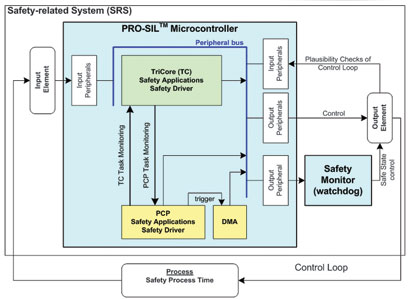
The innovative safety concept is based on a challenge-response technique, where the PCP on the TriCore chip operates as the challenger and the main TriCore CPU executes the tests. Information is passed through a shared memory structure, while the data will be kept diverse and redundant.
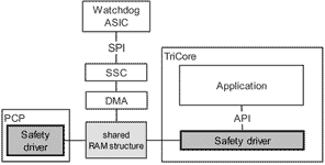
Self-test functions are implemented on the PCP and this is additionally monitored by an external intelligent watchdog (CIC61508) which is connected to the TriCore chip via the SPI (Figure 3). The watchdog device is an effective measure to minimise common-cause failures. The watchdog communicates with the TriCore chip in specified timing windows to check the clock, voltages and correct operation of the TriCore chip as defined in the standards.
On the other side the TriCore monitors the power supply of the CIC 61508 and monitors it for correct operation via remote diagnostic measures. Error detection (hardware failure and task monitoring) is shared between the main TriCore CPU and the PCP.
The PCP software contains the PCP self-test, the C/R (challenge/response) communication, the watchdog communication, a test execution monitor and a task monitor. The SafeTcore library running on the TriCore is a configurable framework that offers test functions to validate the processor and system integrity (Figure 4).
Most of these tests are implemented so that they can run at start time but also at runtime in the background. The typical diagnostic interval time is 6,4 ms. The most complex test is the TriCore CPU self-test. Using this safety concept, an overall diagnostic coverage of 96,5% for this op-code based self-test can be reached, which is significantly better compared to other instruction set tests and has the benefit of being interruptible and of low latency.
SafeTcore test library
The SafeTcore package provides the tools to accomplish two things in parallel – a required certification from SIL1 to SIL3 (or ASIL B-D) and a demanding time-to-market schedule. The biggest challenges for certification are to achieve the required tests on silicon level and to have the documentation to back up the safety case.
The SafeTcore package delivers this through a highly configurable driver library for the TriCore family of devices, combined with the availability of a full set of safety manuals, safety cases and requirements/traceability databases. By using the SafeTcore set of powerful self-test routines that run on the PCP both at startup and cyclically from within an application (Figure 5), the correct operation of the user’s software and the TriCore CPU itself can be verified and proven.
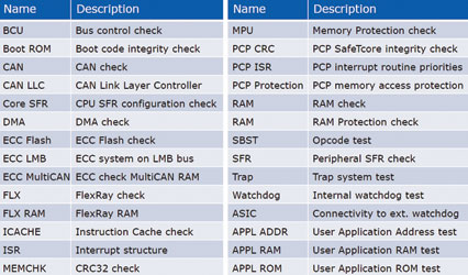
The core test features are combined with detailed peripheral tests and automatic support for the safety monitor chip. The set of software tests in the SafeTcore library also provides operating System monitoring functionality to perform complex task and process flow monitoring, which enables safe execution of code with diagnostic coverage of more than 99%.
The SafeTcore package also includes a safety manual for the integration of the various library elements into the user application and the approval of the safety integrity level.
Watchdog
The CIC61508 can be integrated into various functional safety relevant applications. The watchdog monitors the main microcontroller (eg TriCore chip) by providing features to detect common failure modes of clock, power supply and temperature which may lead to computational errors on the microcontroller. Thanks to its small TSSOP-38 footprint, the CIC61508 is a space-saving and cost-effective option for supporting safety applications.
In a safety-related system using a TriCore MCU, the TriCore main core runs the SafeTcore test software with core and peripherals test, while the PCP monitors the TriCore main core. The CIC61508 external watchdog monitors both cores to identify common causes of failure. As the PCP has already implemented various self-test functions, the TriCore/CIC61508 combination needs only a subset of the functionality offered by the CIC61508.
The test features supported by the CIC61508 are stored in its ROM and include an internal op-code test scheduler/sequencer which generates a sequence of test requests with specific data and checks the response against a user-defined table.
Other monitoring functions include the capability of detecting under-voltage and over-voltage in up to four power domains, the capability to monitor up to eight parallel data comparisons and verification functions, and an operating system task monitor to check the predefined dispatch sequence and execution budgets of all safety-critical tasks.
For more information contact Davis Moodley, Infineon, +27 (0)11 706 6099, www.infineon.com


© Technews Publishing (Pty) Ltd | All Rights Reserved
 printer friendly version