


The theory is simple: process electronics assemblies in spec every time and you will end up with a quality product.
In practice, this is more difficult for numerous reasons, including normal and abnormal process variation, human error and more.
But first, let’s be clear on what our process specifications really are.
Critical components such as LEDs, crystals, bottom-terminated components (BTC) including micro BGAs, and others have very specific process limits that can be challenging to achieve and devastating when missed. Electronics assemblers must fully understand the nomenclature and process window definitions before setting up their assembly machines. Maximum rising and falling slope limits when reflowing PCBs represent a common source of misunderstanding and failures.
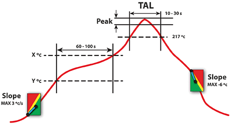
Take an LED component as an example. Figure 1 shows a typical reflow process window or process limits for such a component (the terms slope and gradient are used interchangeably in this article).
Figure 1 appears easy and straightforward, right? Wrong. The devil is in the details, and the downside of getting it wrong is significant. First, a definition of a temperature slope: ‘the rate of temperature change with distance or time.’ In a thermal profile, this will be measured in °C or K (Kelvin) per second.
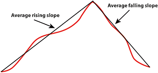
A common mistake is to calculate maximum rising and falling temperature gradients as a linear measurement from the start of the profile to peak temperature, and from the peak temperature to the end of the profile (Figure 2). These calculations are misleading and very different from the maximum slope because they average the various slope calculations along the profile. It reminds me of the old joke about the statistician, with his head in the oven and his feet in the refrigerator, who stated that the average temperature was comfortable.
To find the correct measurement of the slope, we need one more specification: the distance or time over which the slope will be measured. Reading the fine print in the LED component spec limits, we could find the following (as an example): maximum rising slope to be measured over 10 second intervals.
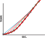
To calculate the maximum rising slope for the LED example above, we need to measure each 10 second slope along the profile from the beginning to peak temperature. To do that we select the profile temperature at 10 seconds, subtract the temperature at 0 seconds, and divide by 10 seconds. Next, we calculate the profile temperature at 11 seconds, subtract the temperature at 1 second and divide by 10 seconds and so forth. The calculations will continue in 1 second increments until the peak.
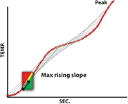
Finally, the highest number of all these calculations represents maximum rising slope. You will note that the 10 second maximum gradient measurement is significantly higher than the average gradient. Similar calculations will be made on the falling slope, but the component supplier will likely specify a different acceptable limit along with new calculation guidelines. The cooling section of the profile has a shorter duration and may be susceptible to more volatile temperature variations. The component specification may call for maximum falling slope measurements over a 5 second interval instead.
The use of average instead of maximum slope calculations will be misleading, and it risks component damage. What makes this particularly worrisome is that stressing LEDs or other optoelectronic and electronic components may introduce latent defects that enable the PCB to pass the factory’s quality inspection, but may fail prematurely when in use.
This may seem very complicated, but with modern profiling software it is straightforward. The calculations are made in a fraction of a second. You just need to study the specs and set the profiling software to perform slope calculations at the component and solder paste suppliers’ specifications for time interval. The 10 and 5 second specification used in this article are only examples. Make sure that the profiling software is capable of measuring the maximum slope over any duration limit. If there are several temperature-sensitive components with different specs, two options are available:
1. Use the most stringent specification for all components.
2. If the profiler supports different specs for each thermocouple (TC), you can attach the TCs to the critical components, making sure all of them are within their individual specs. This will be easier to achieve than the ‘lowest common denominator’ approach in the first method.
The larger challenge will be to set up the reflow oven to achieve a profile that accommodates the more demanding slope specs when using the correct calculations. Again, modern profiling software with prediction algorithms will do a good job of automatically selecting the appropriate oven recipe.
If, however, the slope specifications are defined for you by your client, and your reflow oven is not capable of achieving them even with powerful prediction software, then you may need to investigate further. Ensure that everybody involved is clear on the full definition of your thermal process window and the correct methods to calculate it. This is not a discussion on semantics but whether you are running your production in or out of spec, with all the risk that it entails.
For more information contact Techmet, +27 (0)11 824 1427, [email protected], www.techmet.co.za
| Tel: | +27 11 824 1427 |
| Email: | [email protected] |
| www: | www.techmet.co.za |
| Articles: | More information and articles about Techmet |


© Technews Publishing (Pty) Ltd | All Rights Reserved
 printer friendly version