Considerations for series connection of IGBT and MOSFET switches
28 May 2008
Power Electronics / Power Management
Information from Ixys
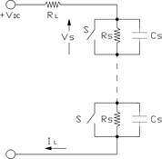
Figure 1 shows the typical RC snubber networks for voltage sharing for switches (S) connected in series in a capacitive discharge circuit. A static voltage sharing resistor RS is required so that the switch with the lowest leakage current is not forced into avalanche and a dynamic voltage sharing capacitor CS is needed so that the slowest switch is not forced into avalanche voltage breakdown during turn-on. A compromise must be reached between the number of switches in series, values for RS and CS and cost of the total switch.
The values of the resistors RS and capacitors CS can be computed from the following:
1. Static voltage sharing resistor RS:
RS ≤ (nVS(MAX) – VDC)(n – 1)-1 IS-1
where: n = number of devices in series
VS(MAX) = maximum allowable voltage across a switch (normally 80% of the maximum switch voltage rating)
IS = maximum leakage current of a switch.
Power dissipation in resistor RS:
2. Dynamic voltage sharing capacitor CS: Assuming no reverse current flow through the switches, then the major factor to consider in sizing capacitor CS is the voltage buildup on the last switch to turn-on. It is desirable to prevent the MOSFET from avalanching in order to limit its turn-on losses. The worst case scenario is that the switch sustaining the highest voltage is also the slowest to turn on.
Then:
where: ΔV = Avalanche voltage - VS(MAX)
DtD(ON) = difference in turn-on times
Solving for CS:
Further reading:
Schneider Electric partners with Drakenstein Municipality
Schneider Electric South Africa
Power Electronics / Power Management
Drakenstein Municipality, situated in Paarl in the Western Cape, is one of the first distribution utilities globally to implement Schneider Electric’s green, SF6-free RM AirSeT switchgear with pure air technology and native digital connectivity.
Read more...
E-Mobility: navigate safety, interoperability and conformance
Concilium Technologies
Power Electronics / Power Management
Although the concept of electric vehicles is not a new one, the market remains in its infancy, and is not well-regulated or fully operational. This presents a number of challenges for manufacturers throughout the EV and EVSE ecosystem.
Read more...
Webinar: Decarbonise with industrial drives
Power Electronics / Power Management
Infineon's TRENCHSTOP IGBT7 and CoolSiC technologies increase the efficiency of your industrial drive design, ultimately resulting in cost savings for you, and a more sustainable future for all.
Read more...
Analysis of switch-mode power supply: inductor violations
Altron Arrow
Editor's Choice Power Electronics / Power Management
Common switch-mode power supply (SMPS) design errors are discussed, and their appropriate rectification is specified, with details on complications that arise with the power stage design of DC-DC switching regulators.
Read more...
Compact PCB-mount SMPS
RS South Africa
Power Electronics / Power Management
Traco Power’s 5W PCB-mount switch mode power supply (SMPS) offers high efficiency, and is well suited for a variety of applications in the automation, electronics, electrical and mechanical industries.
Read more...
AC-DC brick PSU
Conical Technologies
Power Electronics / Power Management
These PSUs have a typical efficiency of up to 92%, and a power factor value of up to 0,99. They are available in
12, 24, 28, 48 and 54 V output versions.
Read more...
5 kW switching PSU range
Conical Technologies
Power Electronics / Power Management
Mornsun has released a new switching power supply range, the LMF5000-25Bxx, which has a 5000 W capacity, and features universal AC input configurations.
Read more...
Reliable charging range
Current Automation
Power Electronics / Power Management
Whether you’re powering essential electronics, keeping emergency equipment operational, or maintaining the performance of critical machinery, the need for dependable charging solutions cannot be overstated.
Read more...
Microchip expands its mSiC solutions
EBV Electrolink
Power Electronics / Power Management
The highly integrated 3,3 kV XIFM plug-and-play digital gate driver is designed to work out-of-the-box with high-voltage SiC-based power modules to simplify and speed system integration.
Read more...
Dual-port USB-C power delivery solution
Altron Arrow
Power Electronics / Power Management
Infineon’s CYPD7272-68LQXQ is the tray packing option of the company’s dual-port USB-C power delivery solution and features an integrated dual-port USB-C PD + DC-DC controller.
Read more...


 printer friendly version