


The personal computer (PC), currently the standard information processing device for office and home use, communicates with most peripherals using the universal serial bus (USB).
Standardisation, cost and the availability of software and development tools have made the PC very attractive as a host processor platform for medical and industrial applications, but the safety and reliability requirements of these growing markets – especially regarding electrical isolation – are very different from the office environment that has historically driven the design of the personal computer.
In the early days, personal computers were provided with serial and parallel ports as standard interfaces to the outside world. These legacy standards had been inherited from the earliest mainframe computers. Another available communication standard, RS232, though slow, fit well into medical and industrial environments because it allowed easy implementation of the required robust isolation. Its low speed and point-to-point nature were tolerated because it was universally available and well supported.
USB, which has come to replace RS232 as a standard port in personal computers and their peripherals, has features that are far superior to the older serial port in nearly every respect. It has been difficult and costly to provide the necessary isolation for medical and industrial applications, however, so USB has been principally used for diagnostic ports and temporary connections.
This article discusses various ways of applying isolation with USB. In particular, a new device, the ADuM4160 USB isolator, is now available from Analog Devices. This product allows simple, inexpensive isolation of peripheral devices – especially including the D+ and D – lines – increasing the usefulness of USB in medical and industrial applications.
About the universal serial bus (USB)
USB is the serial interface of choice for the PC. Supported by all common commercial operating systems, it enables on-the-fly connection of hardware and drivers. Up to 127 devices can exist on the same hub-and-spoke-style network. Many data transfer modes handle everything from large bulk data transfers for memory devices, to isochronous transfers for streaming media, to interrupt-driven transfers for time-critical data such as mouse movements. USB operates at three data transfer rates: low speed (1,5 Mbps), full speed (12 Mbps) and high speed (480 Mbps). When this system was created, consumer applications were emphasised; connections had to be simple and robust, with controllers and physical-layer signalling absorbing the complexity.
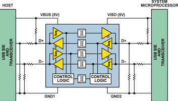
The USB physical layer consists of only four wires: two provide 5 V power and ground to the peripheral device; the other two, D+ and D–, form a twisted pair that can carry differential data (Figure 1). These lines can also carry single-ended data, as well as idle states that are implemented with passive resistors. When a device is attached to the bus, currents in the passive resistor configuration negotiate for speed, as well as establish a non-driven idle state. The data is organised into data frames or packets. Each frame can contain bits for clock synchronisation, data type identifier, device address, data payload and an end-of-packet sequence.
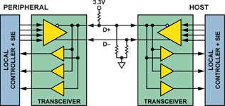
Control of this complex data structure is handled at each end of the cable by a serial interface engine (SIE). This specialised controller – or portion of a larger controller, which usually includes the USB transceiver hardware – takes care of the USB protocol. During enumeration, when a peripheral is first connected to the cable, the SIE provides the host with the configuration information and power requirements. During operation, the SIE formats all data according to the required transfer type, as well as providing error checking and automatic fault handling. The SIE handles all flow of control on the bus, enabling and disabling the line drivers and receivers as required. The host initiates all transactions, which then follow a well defined sequence of data exchanges between host and peripheral, including provisions for when data is corrupted and other fault conditions. The SIE may be built into a microprocessor, so it may provide only the D+ and D– lines to the peripheral.
Isolating this bus presents several challenges:
1. Isolators are nearly always unidirectional devices, while the D+ and D– lines are bidirectional.
2. The SIE does not provide an external means to determine data transmission direction.
3. Isolators must be compatible with the pull-up and pull-down functions of passive resistors, making them match across the barrier.
Typical approaches to isolate the USB largely seek to sidestep the above challenges.
A first approach: Move the USB interface completely out of the device that requires isolation (Figure 2). Many devices interface generic serial buses to USB; an RS232-to-USB interface is shown in this example. The SIE provides a generic serial-interface function; isolation is implemented in the low-speed serial lines.
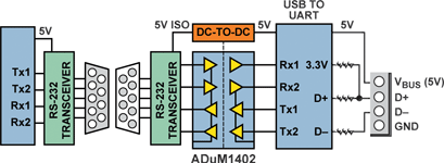
This approach does not capitalise on the advantages of USB, however. All that has been created is a serial port that can be loaded on-the-fly. The interface IC could be customised through firmware changes to identify the peripheral, allowing a custom driver to be created, but each peripheral would require a custom adapter. Unless the adapter was permanently affixed to the peripheral, it would be a servicing nightmare. In addition, the speed of the interface would be limited to that of standard RS232 – not close to the throughput of even low-speed USB.
A second approach: Use a standalone SIE that has an easily isolated interface (Figure 3). Several products on the market use fast unidirectional interfaces, such as SPI, to connect an SIE to a microprocessor. Digital isolators, such as the ADuM1401C four-channel digital isolator, will allow full isolation of an SPI bus.
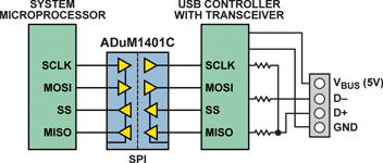
The SIE contains buffer memory that can be filled by the SPI bus, so the operating speed of the SPI can be largely independent of the speed of the USB. The SIE will negotiate with the USB host for its highest possible connection speed and will dispense data at the negotiated bus speed until it runs out of buffered data. The SIE will then tell the host to retry if more data is expected, allowing time for the SPI interface to refill the buffers for another transfer cycle. Though very effective, this scheme usually requires modifications to peripheral drivers, as well as bypassing existing USB facilities built into the peripheral’s microprocessor. This solution is expensive in terms of components and board space.
A third approach: If the microprocessor’s SIE uses an external transceiver, the data and control lines to the transceiver can be isolated (Figure 4). But USB requires as many as nine unidirectional data lines between an SIE and its transceiver. This represents a significant expense in high-speed digital isolators.
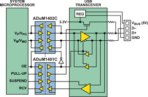
In addition, the fastest available digital isolator works at about 150 Mbps. Though much faster than low- and full-speed USB, it cannot handle high-speed data, limiting the speed range of the USB interface. This solution is fully compatible with the USB drivers provided for the microprocessor’s SIE, lowering development costs, but the many isolation channels required make it expensive to implement. Market trends toward increased integration will obsolete this type of transceiver interface.
A fourth approach: Insert the isolation directly into the D+ and D– lines (Figure 5). This allows D+/D– isolation to be added to existing USB applications without rewriting drivers or adding a redundant SIE, a significant advantage over the other approaches.
Isolating the D+ and D– lines complicates the situation, however, as the device must be able to handle flow of control like an SIE, as well as permit application of pull-up resistors and speed determination across its isolation barrier. It should also operate without calling for the overhead of additional device drivers.
These challenges have been met with the ADuM4160 USB isolator (Figure 6), a new chip-scale device that supports direct isolation of low- and full-speed USB D+ and D– lines.
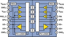
Analog Devices iCoupler technology is particularly well suited to construction of a USB isolator. The primary challenges in developing a USB isolator are properly determining the direction of data transmission, and when to disable drivers to allow an idle bus state. The packet-oriented nature of USB data allows a simple method of determining data direction without the overhead of a complete SIE. When the bus is idle, pull-up and pull-down resistors hold the USB in an idle state with no buffers driving the bus.
The ADuM4160 monitors the upstream and downstream segments of the bus, waiting for a transition from either direction. When a transition is detected, it is encoded and transmitted across the barrier. The data is decoded, and the output drivers are enabled to transmit on the other cable segment. From this first transition, the direction of data flow is identified, and the reverse direction isolation channels are disabled. The isolator continues to transmit data in the same direction as long as data continues to be received.
When the USB packet is complete, special data, the end-of-packet (EOP) sequence, is transmitted. The EOP contains a non-differential signal that should not be included in any data structure. The isolator can distinguish an EOP marker from valid data. This signals that the bus should be returned to the idle state. The output drivers are disabled, and the isolator begins to monitor its upstream and downstream inputs for the next transition – which will set the next direction for data transmission.
In addition, watchdog timers return the isolator to its idle state when a bus error occurs. The ADuM4160 takes advantage of the transition-based isolation scheme, one of the core capabilities of iCoupler technology.
The isolator must also provide support for pull-up and pull-down resistors. Each side of the isolator supports an independent USB bus segment, with all of the bias resistors present in the idle state. The pull-up resistor signals that a new device on the bus needs to go through the initialisation sequence, called enumeration. Knowing the operating speed of the peripheral and the time when the pull-up should be connected allows enumeration to begin in a controlled manner.
Several factors can affect the status of the upstream pull-up resistor. Different combinations of available upstream and downstream power-supply voltage are possible. The isolator is designed to give predictable operation in all specified combinations of available power. A peripheral would want to delay application of the upstream pull-up resistor at times – if it needs to complete its own local initialisation prior to starting the USB enumeration, for example. The ADuM4160 provides a control pin on the downstream side of the part to allow the peripheral to determine when enumeration occurs.
Other features available in the device include the ability to run from either a 5 V or 3,3 V power source. So only one power supply is required in the peripheral; it can be either voltage. The ADuM4160 has also been designed with rugged ESD protection to allow hot plugging of D+ and D– pins to connectors without external protective circuitry in most cases.
The ADuM4160 will likely be used in one of three ways:
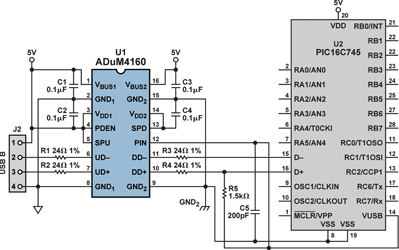
1. It will be installed in a peripheral to isolate its upstream port. The ADuM4160 was designed with this configuration as the base application. It leads to the simplest power and control configurations (Figure 7).
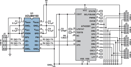
2. It can be used to isolate a hub and therefore all of the peripherals downstream of the hub (Figure 8).
3. It can be used in an isolated cable configuration (Figure 9).
The following illustrations show how the ADuM4160 will be connected in each of these applications.
In the peripheral application (Figure 7), where the peripheral has its own source of power, almost no power is required from the USB cable – about 10 mW to run the isolator’s upstream side and the pull-up resistor. Since the peripheral operates at a single speed, the isolator is hardwired for the desired speed setting, either full speed or low speed. If the peripheral port happens to be high-speed capable, then it sends a high-speed ‘chirp’ pattern during enumeration. This would normally initiate negotiations for high-speed operation, but the ADuM4160 blocks the chirp signal and automatically forces the high-speed peripheral to operate at full speed. For low-power peripherals that do not have their own supply, an isolated DC-DC converter can be used to supply the peripheral and the ADuM4160, drawing power from the USB cable.
Used as a hub isolator (Figure 8), the ADuM4160 treats the hub as its peripheral. The device is set to full speed; the rest of the application is similar to the standard peripheral case discussed above. The hub will be forced to operate at full speed by the isolator’s intervention in its chirp function. The hub IC will allow connection to combinations of low- and full-speed devices, even though the isolator runs at a fixed speed. The hub provides power to the isolator’s downstream port, and enumeration can begin either at power-up or on a delayed basis. The hub usually requires more power than can be supplied by the upstream cable via an isolated DC-DC converter.
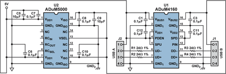
Driving an isolated USB cable (Figure 9) requires use of a DC-DC converter to supply power to the downstream port and cable. To satisfy the requirements of the USB specification, the downstream segment of the cable must provide 5 V power to the pull-up of the peripheral device. An isolated DC-DC converter can provide this power with enough left over to provide power for downstream devices with low power requirements.
Figure 9 shows the use of an ADuM5000 isoPower device. In this application, the hard-wired speed pins of the ADuM4160 become somewhat inconvenient. The cable will only operate at one USB speed at a time; it must be rewired to switch speed modes, either manually, by simple switches, or with more elaborate circuits, depending on the end user’s requirements.


© Technews Publishing (Pty) Ltd | All Rights Reserved
 printer friendly version