There are many benefits in using fibre-optics as a data transmission medium rather than copper cable. In this article, using the example of a fibre-optic system for CCTV, David Archer, the technical manager of Fiber Options (Europe) takes a close look at the optical loss budget, the system tests and commissioning, and performs a cost comparison between fibre and copper.
The optical loss budget
It may seem odd to be carrying out the loss budget calculations at a late stage in the design process of the installation, but in fact this can only be achieved with any accuracy once the complete cabling infrastructure has been defined. The objective is to calculate the worst-case link path loss (usually the longest) and ensure that the chosen transmission equipment has adequate performance to cover this with a reasonable margin in hand.
This is quite simple, and merely involves adding together the dB losses of all the components in the link, including fibre attenuation (dB/km x length in km), plus both connector and splice losses. The greatest difficulty is often simply one of gleaning the relevant loss figures from a sheath of manufacturer's data sheets; the 'rule-of-thumb' values listed in Table 1 may be helpful in this respect. Note that where the system uses two wavelengths simultaneously on the same fibre, eg, for single fibre video and PTZ (pan-tilt-zoom) transmission, the higher attenuation figures should be used for loss budgeting purposes.

Depending on the outcome of this exercise, it may be necessary to re-evaluate the chosen transmission hardware in order to accommodate the predicted path losses. For example, it may be necessary to specify equipment with enhanced optical performance, or failing that, consider a change of wavelength to lower loss transmission window.
System tests and commissioning
Most fibre-optic installers will provide optical test results for the installed fibre-optic infrastructure. As an absolute minimum this should consist of optical power-through measurements for each terminated fibre path - this is equivalent to a continuity test on a conventional copper system using an electrical multimeter. This will be expressed as a path loss in dB, and can be directly compared with the specified performance of the chosen transmission equipment. It is normal to provide a minimum loss margin (equipment capability minus actual loss) of 3 dB, in order to allow for the inevitable ageing process that occurs in the fibre-optic link, particularly in the fibre-optic transmitter.
Many installers also provide OTDR test traces - these are best described as a graphical record of each fibre attenuation, which can be stored for later comparison or analysis. OTDR traces can provide invaluable information, but nevertheless should be regarded as supplementary to, rather than a substitute for, power-through loss measurements. This is because the information they provide is difficult for non-specialists to interpret and can easily be flawed by obscure fibre effects, and is of only limited accuracy.
Under normal circumstances, only minimal system commissioning should be required, assuming that the fibre-optic receivers feature automatic gain control (AGC), thus eliminating any need for manual gain control adjustments
Cost comparison - fibre versus copper
The cost of implementing fibre-optic networks has fallen dramatically over the past few years, so that it is at long last possible to provide meaningful cost comparisons with other transmission media, such as twisted pairs or coaxial systems.
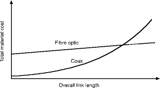
Until such time as cameras and monitors are supplied with both BNC coax connectors and 'ST' optical connectors, fibre-optic links will always be at a price disadvantage due to the cost of providing the external transmission components. This is particularly so for very short links where the cost of the transmission equipment is a large proportion of the total. For links in excess of a few hundred metres, however, fibre-optic systems become increasingly attractive as the cost of providing coax systems increases disproportionately, either due to the cost of providing premium quality cable, or line-amplifiers, or both. This is illustrated in Figure 1.

Thus, there is always a link length, probably between 500 and 1000 metres, beyond which a fibre-optic CCTV network can be justified on cost grounds alone. If the average length is much shorter than this, and your sole criteria for the selection of a transmission medium is minimum cost, then fibre-optics is unlikely to appeal. On the other hand, if other factors such as picture quality, freedom from interference, and vastly-reduced maintenance are also important, then you would do well to consider using fibre in your system.
Elvey Security Technologies is the sole recognised distributor of Fiber Options transmission equipment in South Africa.
For more information contact Elvey Security Technologies, +27 (0)11 401 6700, sales@elvey.co.za
| Tel: | +27 11 401 6700 |
| Email: | info@elvey.co.za |
| www: | www.elvey.co.za |
| Articles: | More information and articles about Elvey Security Technologies |

© Technews Publishing (Pty) Ltd | All Rights Reserved