


An important stage in the development of an electronic circuit is that of component selection. The engineer must choose the best components after defining the functional parameters and operating temperature range of the circuit.
The choice between multilayer ceramic capacitors (MLCCs) or tantalum capacitors is one of these design considerations. In this article we discuss many of the aspects that must be considered. Often, an R&D engineer has little experience in choosing components. At university he or she learns theoretical concepts but receives little practical experience. So, when choosing a capacitor he or she may not appreciate the full complexity of his options.
The issue is, 'How to choose between MLCC and tantalum capacitors in the development of power supply circuits where most of these dilemmas arise'. There are other dielectrics but, because they offer the best cost/performance balance, MLCCs and tantalums predominate.
MLCCs and tantalums have similar uses but are different in their structure and materials. Typically, 0,1 μF to 100 μF values of either are used for decoupling, bypass, shunt and signal filter applications or to reduce high frequency noise. In power supplies they are used for ripple reduction and noise filtering. How well they do so is a function of the dielectric.
Consider an engineer needing a 1 μF capacitor with a working voltage of 25 V. To get the best performance and reliability, whilst considering the known parameters and needs of the circuit, he or she must also consider those of the dielectric. The ability to handle the operating temperature range, the nature and amplitude of electrical spikes and whether to use polarised capacitors or not, are all important design considerations.
Advantages of MLCCs
MLCCs need no temperature derating. In a circuit operating at 25 V and full-rated temperature, a 25 V MLCC can be selected with full confidence.
Selection of a tantalum capacitor is different. There is a linear reduction of the working voltage above 85°C, so that at 125°C the allowed DC working voltage can be as low as two thirds of the nominal value. So, to get the required reliability over the temperature range, manufacturers state that the tantalum working voltage should not exceed 50% of its rated voltage. In the example above this would have to be no less than 50 V.
MLCCs are non-polarised. Electrolytic capacitors are polarised, giving a danger of damage or even explosion if subjected to high reversed polarity pulses, or if they are mounted incorrectly. The permissible reverse voltage on these electrolytics is 15% of the nominal at room temperature, 5% at 85°C and only 1% at 125°C. This is often only shown in some of the manufacturers' application notes, not generally in data sheets.
MLCCs have a wider frequency bandwidth and lower impedance than tantalums, making them more effective in suppressing noise in power lines. The MLCC's impedance reduces by a factor of 10 when the frequency is multiplied by 10 (see Figure 1) and can be a few milliohms. The impedance of tantalum capacitors remains in the hundreds of milliohms above 10 kHz.
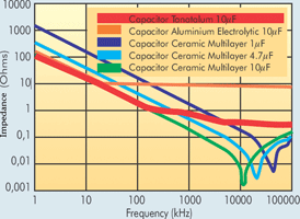
In the past, PSUs needed two capacitors, one high value electrolytic and a lower value MLCC. Now, one high value MLCC in the same size can be used. A single MLCC, giving better frequency response than the electrolytic/MLCC combination provides the required frequency response over a wide frequency band. Today's MLCC can do the whole job.
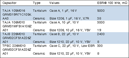
MLCCs have other advantages, particularly at higher frequencies. The ESR (equivalent series resistance) and the ESL (equivalent series inductance) are much lower than those of tantalums. A comparison between the ESR of various ceramic and tantalum capacitors with the same values and voltages is shown in Table 1. The ESR of ceramic capacitors is substantially lower than that of the tantalum equivalents. It is important to appreciate that the lower ESR will prevent overheating of both the device and the circuit, increasing overall reliability. Below 10 kHz the ESR of ceramic capacitors increases, so tantalum or aluminium electrolytic capacitors are recommended in this frequency range.
The parasitic inductance of MLCCs is lower than that of tantalums, reducing harmonics from ripple currents and neutralising noise at higher frequencies. ESR and ESL are affected by the sizes of components. Minimising PCB sizes by downsizing components can affect the circuit's technical performance. As the size of MLCCs is decreased, so the ESR increases and the ESL decreases. Reverse geometry devices can be used to obtain better characteristics, decreasing the ESL without affecting the ESR, when downsizing. You can choose an 0508 capacitor instead of an 0805 or an 0612 device instead of a 1206. The inductance is reduced by a factor of five to 10 as the distance between the capacitor's terminals is reduced (the terminals are fitted on the wider edge of the device).
DC leakage current is a result of imperfect dielectric insulation, causing capacitors to discharge. This is significantly less in ceramic capacitors than in tantalums (0,001 μA compared to 0,5-30 μA).
The DC working voltage of tantalum chip capacitors is limited to between 4 V and 50 V. Ceramic chips are rated from 6,3 V to 200 V with others up to 5 kV. A Tip and Ring capacitor, commonly used in telecommunications, requires a working voltage of 250 V. So clearly ceramic technology offers greater versatility.
Additional recommendations for ceramic capacitors
Choosing the correct MLCC dielectric is essential. A common error is the confusion of the variance of a component's value from its nominal value at 25°C (tolerance), with the dielectric stability over the full temperature range of -55°C to 125°C. The characteristics of MLCCs with different dielectrics and stabilities versus temperature are shown in Table 2.
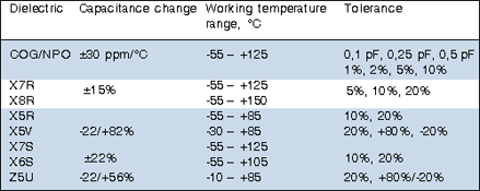
Class I (C0G/NP0) is the most stable at ±30 ppm/°C from -55°C to 125°C. X7R and X5R (class II) dielectrics have stabilities of ±15% between -55°C and 125°C for X7R and -55°C to 85°C for X5R. To allow a direct comparison of the stability of C0G/NP0 with X7R we have to convert the expression of ±30 ppm/°C to a percentage. Multiplying 30 by 100 (the difference between 125°C and 25°C) and dividing the result by 104 (10 000 ppm=1%), we get ±0,3% for class one over the full temperature range compared to ±15% for class two.
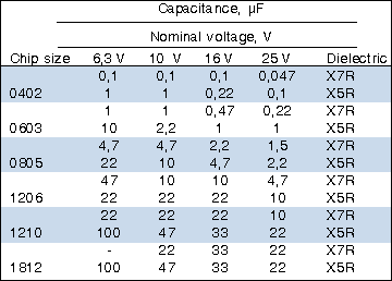
At first glance, stable capacitors (C0G/NP0) look, value for value, more expensive than tantalum and have a maximum value limitation. A maximum of 27 nF to 33 nF can be fitted into a 1206-sized MLCC and the higher values of tantalum can not be attained. X7R/ X5R MLCCs also offer lower maximum values than tantalums. However, because ceramic has better parasitic characteristics than tantalum (ESR, ESL, DC leakage current and frequency characteristics), lower MLCC values meet the requirements of power supplies, giving the performance needed in a fraction of that needed by tantalum.
The technical advances of MLCCs provide higher values in the same small sizes, giving technical and financial benefits when they replace tantalums.
In conclusion, a designer needs to consider all the above before deciding which dielectric he or she will specify. We suggest that MLCCs will be the most cost-effective choice now, with ongoing development increasing their supremacy.


© Technews Publishing (Pty) Ltd | All Rights Reserved
 printer friendly version