


The term ‘test system’ represents millions of different possible configurations of test instruments, software and device under test (DUT) specific test execution programs.
Each test system is created based on a specific technology, application and phase of a product under test development, whether it is in research, validation, verification or manufacturing.
Some test systems are created for consumer products such as smartphones and tablets, and maintain goals of fast throughput, low cost and ease of configuring and updating. Others such as satellite payload test cost several million dollars to manufacture, are complex and must provide high-quality measurements to ensure functionality, accuracy and repeatability of the payload while in orbit.
With these examples and the endless possibilities for test systems in between, one type of test system cannot provide the answer for all test needs. When it comes to test system development, one size does not fit all. This article discusses how test system configurations benefit from a choice of hardware form factors and software products.
Test systems may be benchtop only, modular only, or a combination of both (hybrid) platforms. There are benefits provided by each of the benchtop and modular instrument platforms that suit specific use models. As a consumer device or specialised instrument moves through its life cycle from inception to final test and production, the test needs evolve. Many research and development test systems benefit from easily adjustable benchtop instruments with front panels.
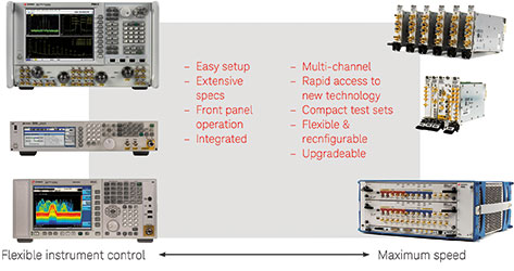
As the device approaches its final design, the measurements become routine and there is an expectation for more repeatable results. Test systems often evolve from benchtop to modular configurations for higher volume test as goals shift to fast throughput, more connections for channels or devices, and smaller size.
Benchtop
Product research and development engineers benefit from using benchtop instruments that provide the convenience of a ready-to-use tool. Benchtop instruments have a familiar front panel display with adjustable buttons and knobs which can be used to explore and modify a device’s functionality and performance.
Measurements or test adjustments are determined and made in a thoughtful, progressive process where improved product development or performance is the main goal. Confidence in the accuracy of the benchtop instruments’ measurements is vital to the successful development of the device.
Measurement application software that works with benchtop instruments provides additional benefits: expertise in measurement algorithms, easy configuration and the ability to add or modify a measurement to the test sequence specific to the device. Application software that complements benchtop instruments can save time and provide accurate, repeatable and reliable test sequences.
Modular
High-volume device test in manufacturing benefits from the use of modular instruments programmed for automatic measurement sequences where stimuli can be adjusted and results monitored through software. Multiple devices may be tested simultaneously and are best addressed by a modular system with a greater number of stimulus and measurement channels.
Measurement data from multiple channels or devices can be quickly transferred and synchronised through a single, high-speed modular backplane resulting in shorter test times and lowering manufacturing test costs. Phase coherency for complex applications, such as beamforming test, can be easily accommodated with appropriate triggers and methods.
The space and power requirements for multiple modular instruments are much less than the equivalent benchtop instrument configuration. Modular multi-channel test systems do not carry redundant, multiple displays and power supplies. This makes modular easier to accommodate in a production environment.
Hybrid
A challenge for many test engineers is managing both hardware and software test system changes, when transitioning from use in research and development to manufacturing. Selecting benchtop and modular products that are similar in measurement ability and command structure can save enormous amounts of time and cost, and prevent the need for rewriting software and the development of a completely new test system.
Regardless of the instruments and software selected for a test system, a test engineer’s goal is to use instruments and software that provide proven and consistent results. Using a test system software application that provides measurement expertise for both benchtop and modular instruments is even more beneficial in achieving a similar test system from R&D to manufacturing.
A single hardware platform is rarely the right answer for every test scenario. That’s why Keysight Technologies provides traditional benchtop instruments as well as a selection of modular instruments and software. The company supplies a growing portfolio of PXI and AXIe modular instruments based on the same measurement science used to develop traditional benchtop instruments. In these modular form factors, today’s measurements support new product capabilities across analog, digital, RF and microwave technologies.
Why modular?
Modular instruments, such as PXI and AXIe, are becoming more widely used in test systems for several reasons. PXI and AXIe platforms address engineers’ demand for greater measurement speed, including data transfer and synchronisation across instrument modules.
PXI is able to provide more functionality, stimulus input and measurement outputs, with more channels in a smaller form factor than benchtop instruments. The PXIe chassis backplane is based on the computer standard PCI Express (PCIe) architecture and takes advantage of embedding this widely used technology for data rates and throughput.
The PCIe bus is made up of links, with each link containing one or more lanes (x1, x2, x4, x16 or x32). An example of the common terminology for an 8-lane link would be ‘by 8’. The PCIe bus is a point-to-point bus which connects a single upstream and single downstream component, which provides higher bandwidths than a multi-drop topology bus structure.
PCIe 1.0 has single lane transition rates of 2,5 Gbps. After encoding, this results in a theoretical data rate of 250 MBps. PCIe 2.0, also known as PCIe Gen2, runs at twice the rate, and can achieve up to 500 MBps per lane. Gen3 can run even faster, and due to more efficient encoding is expected to attain rates approaching 1 GBps. These data rates are for a single x1 link. For a x8 PCI Express Gen2 link, a 4 GBps data bandwidth can theoretically be achieved.
Advanced TCA Extensions for Instrumentation and Test (AXIe) is another modular instrumentation standard. With up to 62 differential signal lines on an AXIe local bus, it provides an extremely large data bandwidth for data-intensive applications such as streaming data from a digitiser to an FPGA or memory module. These dramatic speed capabilities are required to achieve the test speeds desired for new and future test applications.
As the number of desired channels in a test system increases, design and test become more complicated, requiring better channel-to-channel correlation and additional equipment to address multiple channels. PXI and AXIe modular instruments are ideally suited for high channel count applications due to their easily integrated instrument architectures, small form factor, scalability and module-to-module synchronisation.
Module-to-module synchronisation, in particular, provides advanced measurement capabilities for more challenging multi-channel applications. The compact and scalable configuration of PXI allows engineers to build the test system they need today and add modules for more channels or instruments as their test system requirements change in the future.
Synchronisation of multiple instruments can be a challenge. Multi-channel applications require very tight instrument-to-instrument skew which can be more readily achieved across a common backplane. The PXIe and AXIe modular architectures promote peer-to-peer interaction, including data transfers and triggering through the PCIe backplane.
PXIe timing signals are differential and route to the high-speed backplane through advanced differential fabric (ADF) connectors. Because of the higher speed capabilities of the ADF connectors and differential nature of the signals, tighter module-to-module skew can be attained.
PXIe specifies a maximum slot-to-slot skew of 200 ps for the differential star triggers as well as the 100 MHz reference clock. Triggers and time-base clocks routed over the PXIe backplane enable time and phase synchronisation between instruments for challenging multi-channel configurations.
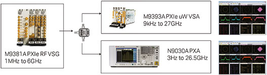
An example of a PXIe test system for a high channel count application, is the multiple antennas test system where an RF test set is configured with multiple vector signal analysers (VSA), vector signal generators (VSG) or both. The use of modular instruments for this application helps achieve:
• Fast download of waveforms through the PXIe backplane for accelerated multi-channel test.
• Compact and scalable configuration that allows upgradability for more channels or features as test requirements evolve.
• Time synchronised VSAs and VSGs for spatial multiplexing MIMO.
• Combined benefits of the high-speed PXIe backplane and increased RF performance of modern modular products for highly accurate measurements with greatly reduced time.
• Synchronised, phase-coherent measurements for RF systems with multiple sources or receivers.
As PXI and AXIe architectures have progressed, more test capability through new modular instruments and software have made setup and test execution easier, faster and more reliable, and provided engineers with the tools they need to complete test setup and start testing faster.
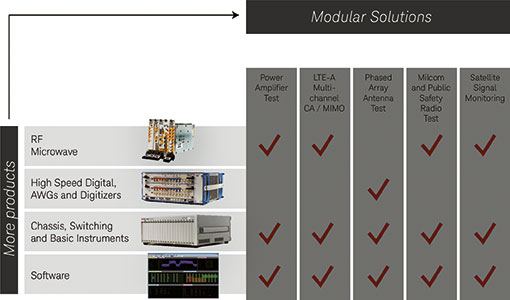
Modular reference solutions
PXI and AXIe offer incredible flexibility with open options for integrating many instruments and software. With so many choices and combinations of products it may be overwhelming for test engineers to select and verify the performance of combined modules and software.
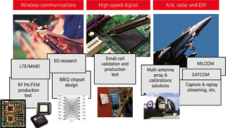
Keysight provides Reference Solutions – a proven recipe of hardware and software configurations for specific applications. The market-validated recipe optimises the use of precision modular products, benchtop products and software for applications such as power amplifier test, LTE-A multi-channel CA/MIMO, phased array antenna test, milcom and public safety radio test, and satellite signal monitoring.
The primary advantage of the Reference Solutions is the time saved in selecting and integrating products. As new test systems are added or created the Reference Solution could help engineers meet stringent schedules and test requirements by providing high-performance test configurations.
Measurement software and enhancing the test process
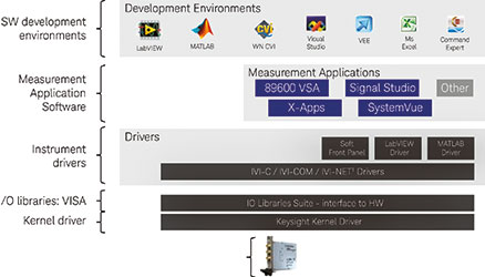
Modular software applications, utilities and companion tools add compelling capability for avid test system programmers and non-programmers alike. Software controls modular test systems and also provides the means to view and analyse the results. Leveraging application software is common with test engineers who want to get to results faster by not re-writing software.
Modular instrument software drivers give test system programmers the ability to create or add specialised control and measurements. Both the application software and the instrument drivers provide flexibility to address configuration and programming needs specific to the test applications.
Keysight instrument drivers and measurement software applications are designed to work on benchtop and modular instruments alike, which provides software continuity for test systems that originate in R&D and evolve through production test.
An example of application software that can be used with benchtop and modular instruments is Keysight’s X-Series Measurement Application Software, which consists of specialised applications like GSM/EDGE/Evo, W-DDMA/HSPA+, LTE FDD and more. These applications can be used without writing a single line of code, which makes modular instruments nearly as easy to control as benchtop instruments with front panels.
In many cases, more than one type of measurement application software is needed within a test system. A few examples may be when the system needs to provide additional spectrum measurements, test an unsupported signal format or import measurements from another application. This creates a challenge for test engineers who must now integrate the different software applications. Keysight ensures software interoperability with other applications and can be used in different programming environments.
PXI standards ensure interchangeability across instrument manufacturers
The PXI System Alliance specification includes the PXI standards and framework to ensure interoperability of PXIe test instrumentation. The PXI standard builds upon existing standards including PCI and Compact PCI. Including the existing widespread PCI standard is beneficial to the PXI architecture for a few reasons:
• Test and measurement engineers working with PXI benefit from the readily available PCI components, discovery methods and software toolsets developed for PCI bus users.
• The same high-speed communication busses are used in PCs and PXI leverages the bus interconnect, device discovery and instrument driver installation.
• Many mechanical attributes are defined including enclosure slot spacing, module form factor, connector styles and pin-outs.
• PXI extensions include features to support high-performance trigger and synchronisation capabilities of PXI Express along with backward compatibility requirements for older PXI modules.
• These standards ensure that the integration of modules and chassis in a test system can be from multiple vendors.
PXI and AXIe test systems are able to take advantage of using the standard PCI bus common tools. For the modular PXI and AXIe systems, the standard tool, Windows Device Manager, is used to probe the bus status, including the status of connected modular instruments. The Device Manager will show any PCI based device connected to the bus even before module instrument drivers are installed.
Once the instrument drivers are installed the individual PCI devices appear with the appropriate icons and basic manufacturers’ information. If a PCI modular instrument is connected but the driver is not installed, or there is an issue with the installation, the device appears in Device Manager with a yellow warning icon.
A benefit of PXI and AXIe is that the architecture is based on the standard PCI bus in the Device Manager – a readily available tool for inspecting the connection of modular instruments.
Benefits of an open software architecture
The Device Manager is good for an initial view of the modules inserted into the PXI chassis backplane. However, it is not able to designate a specific chassis or slot locations of modules. In a case where there are several of the same type of modules inserted into a chassis, the test engineer can use Keysight’s Command Expert to determine where each specific module is located.
The software tools allow users to assign alias names to the modules, which simplifies addressing the correct module when programming automated test programs. These software tools support interoperability by ensuring modules from different vendors will be recognised and can be programmed to perform in the same test system.
Modular instruments’ soft front panels are tools that allow test engineers to easily connect to, configure and provide a limited amount of control and a view of measurements for initial startup and to verify configurations or measurements. Other software utilities such as IO libraries, IVI drivers and Command Expert provide a means for test engineers to program in the software environments they choose and offer the flexibility and tools to develop systems tests specific to their applications’ needs.
| Tel: | +27 12 678 9200 |
| Email: | info@concilium.co.za |
| www: | www.concilium.co.za |
| Articles: | More information and articles about Concilium Technologies |


© Technews Publishing (Pty) Ltd | All Rights Reserved
 printer friendly version