


Graphic artists want to create accurate colour matches to capture their artistic work and reinforce branding consistency.
But accurate presentation of colour on different equipment and media still remains a challenge. There are various ways to express colour values, including CMYK, RGB, CIE and HunterLab. Any given colour can be described with three different variables, due to the three different types of cones in the human eye.
A popular way of representing colour is with the CIE 1931 XYZ colour space diagram, where Y is luminance or brightness and the values of X and Z form the chromaticity. Grey and white have the same chromaticity but differ in luminance. The result is a three-dimensional colour space that covers all the colours that can be perceived by the human eye.
Red, green and blue LEDs are capable of producing a wide range of colours but achieving individual colours can be difficult, as can moving smoothly from one colour to another. However, a microcontroller can be programmed to use a slider to create most of the colours available or it can use the CIE 1931 colour space chromaticity diagram, shown in Figure 1.
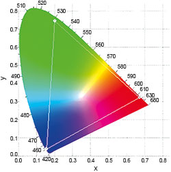
A property of the diagram is that if you have two colours and connect them in a straight line, by mixing the colours in different amounts, you can create any colour along the line. This is why blue LEDs commonly use a yellow phosphor so they can create white light.
When using RGB lighting components to create colours that appear on the chromaticity chart, it confines the achievable colours to a triangle, referred to as Maxwell’s triangle and shown in Figure 1. The range of colours that can be produced is known as a gamut. This is not completely accurate if you are looking at the diagram on a computer screen as that restricts the range to the gamut of the monitor. The white spot at the centre is small and the ability to produce clean white light is a good indication that proper colour mixing is being performed.
Colour mixing
Colour mixing can be achieved using a PIC12F1572 processor from Microchip. This device has three 16-bit pulse width modulators (PWMs) that allow precise control over each RGB LED to achieve the smooth transition between colours even at low luminosity. Colour mixing software lets the designer specify the colours and the processor performs the necessary calculations.
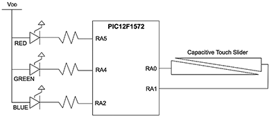
A demonstration board is available to help designers create this using mode one HSVW slider operation. HSV refers to hue, saturation and value, and the W indicates that it has been modified to include white. It can also be reconfigured for mode two, which involves using a chromaticity chart selector. The board can be powered either through a USB connection, a 3 V lithium coin cell or an AAAA battery. The circuit diagram for such a board configured as an HSVW slider is shown in Figure 2.
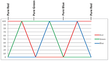
When first powered in slider mode, the board cycles through the HSVW colour wheel. After a period of time, the LEDs start blinking to conserve battery power. The slider on the edge of the board can be used to select a colour to display. Figure 3 represents the colour wheel as modified to include white.
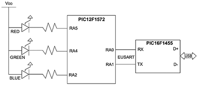
In this mode, the RA0 and RA1 pins in Figure 2 are configured to work with a capacitive touch slider. This lets a finger press and slide action select different colour values, though limited to one-dimensional colour selection. In mode two, the desired colour is picked from an on-screen chromaticity chart, such as the one in Figure 1. Now the RA0 and RA1 pins are configured as EUSART serial interfaces with the values passed to the board via a USB serial connection. A PIC16F1455 converts the USB messages to a EUSART 9600baud format. The setup in this mode is shown in Figure 4.
If a colour is specified that does not fall into the colour gamut of the LEDs, then the function will return an error message and the colour output will not be updated. If the colour is within the colour gamut, then the new colour will be displayed.
Tuning
The resistor values need to be set so that each colour is displayed with the same amount of lumens. For this demonstration, they were calculated at 202 Ωfor red, 325 Ω for green and 61 Ω for blue. Each LED was measured using a chroma meter for colour value.
Luminous intensity can also vary due to temperature, and these variations can be quite large depending on the LED type. This needs to be considered in the final application, especially if it is outdoors. The human eye can detect flicker at about 200 Hz. Intermodulation can also occur with 50 and 60 Hz lighting. It is thus recommended that LED lighting switches at above 200 Hz. In the case of the PWM peripherals on the PIC12F1572, the period is well above that at which flicker can be detected.
A PWM peripheral varies the length of time a particular load is turned on. The ratio of the on time to the PWM period is called the duty cycle and corresponds to the percentage of power that is delivered to the load. Controlling power with a PWM is generally recognised as a precise and efficient method of regulating power output.
Chromaticity chart
The board has been designed to demonstrate a range of colours that appear on the chromaticity chart. These are converted to RGB values, which are colour-mixed to create the resultant colour. Individual LEDs of red, green and blue colours have their duty cycle or brightness controlled through the PWM peripherals. Each individual PWM has 16 bits of resolution, allowing for smooth colour transitions even with very low duty cycles.
The software is structured such that serial messages are received, and the data are used to call the ColorMix routine. This is computationally intensive and takes about 7,7 ms (with 16 MHz oscillator clock) to compute the PWM values. If this routine was used to compute continuously changing colours, the update rate would slow to 130 Hz, and would degrade the smoothness of the changes.
The ColorMix routine was developed in C. The PIC device does the matrix inversion, multiplication and scaling to produce the desired colour. All calculations are done as integers. Scaling is done throughout, so that values will not overflow the long 32-bit variable type.
Hardware configuration
The demonstration board is configured and programmed from the factory for operation in slider mode. To operate the board in this mode, the PIC12F1572 must be programmed with the RGBSlider software, and the PIC16F1455 must be erased.
To operate the board in the chromaticity selector mode, the PIC12F1572 must be programmed with the RGBChroma software, and the PIC16F1455 must be programmed with the RGBChroma USB software.
| Email: | willem.hijbeek@tempetech.co.za |
| www: | |
| Articles: | More information and articles about Tempe Technologies |


© Technews Publishing (Pty) Ltd | All Rights Reserved
 printer friendly version