


One of the advantages of a metal over capacitive (MoC) system is the flexibility of its sensors. Literally hundreds of sensor designs are possible, and the same look and feel can be achieved using various implementations. With this dizzying array of potential, it can be difficult to focus on a specific design unless the designer is acquainted with the design options and their strengths and weaknesses. Consulting with a mechanical engineer is recommended because they will be more knowledgeable about available materials, their characteristics and manufacturing processes.
The basis of an MoC touch system could be an mTouch capacitive sensor from Microchip with the associated electronics and software. The difference in an MoC design is the replacement of the user’s finger with a conductive target layer, suspended over the capacitive touch sensor by a thin spacer. When the user presses the target, it deforms slightly – less than 10 m – towards the sensor, creating a detectable change in the sensor capacitance. The capacitive touch interface (electronics and software) detects the change in capacitance and reports the press to the system.
This means the sensor is electrically isolated from the environment, reducing noise, proximity and crosstalk problems. The grounded target provides a non-destructive path for ESD (electrostatic discharge) energy. The isolation of the sensor from the environment also eliminates problems with water. Because physical force is needed to actuate the sensor, it can be used for braille applications and by users wearing gloves. The metal covering can also give the final product a more professional look and feel.
Building a sensor system
To build an MoC sensor system, a standard capacitive sensor, a spacer with a hole over the sensor and a conductive fascia and target are needed. Figure 1 shows a typical sensor stack-up. Here, the target provides the conductive second plate of the capacitive sensor and the elastic flex required to return the layer to its original position upon release.
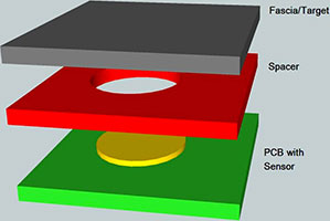
The fascia is the top surface of the assembly with the marking and legends for the button. The target is the conductive layer that provides the second conductive surface for the sensor capacitor. Together, they provide information to the user, the grounded second layer of the sensor capacitor and the mechanical elasticity of the button.
Key points to consider in choosing the material for the fascia and target include how much actuation force is needed to press the buttons; the desired physical appearance of the fascia; environmental factors; whether the button needs to be backlit; and whether backlighting of the fascia and target is required. It is often best to look at the design of the fascia and target together as these usually have to work closely together to operate properly.
The simplest implementation is a single metallic layer acting as both the fascia and target. The fascia layer can either be the markings on the top of the metallic target or a printed film bonded to the target. The single layer of metal provides all the mechanical elasticity for the button and the grounded second plate of the sensor capacitor (target). Figure 1 shows a typical example of a single layer metal stack-up.
The actuation force is determined by the relationship between the thickness of the metal of the fascia and target, the size of the buttons, the elasticity of the metal used, and any back-etching of the fascia and target. For the most part, the size of the button and the thickness of the material are the primary factors.
A significant factor that determines the actuation force of the button is the elasticity of the metal in the fascia and target layer. For example, stainless steel is flexible, but not as flexible as aircraft-grade aluminium. Aluminium, on the other hand, has a lower yield strength, so it is more susceptible to denting and dimpling when subjected to high actuation force. As a result, the choice of material is a trade-off between sufficient elasticity for a low actuation force and yield strength to prevent damage when subjected to high actuation forces.
For appearance, modern silk screen and coating techniques allow a sheet of metal to look like anything from granite to wood. The surface of a metal fascia can be completely or selectively plated with other metals for appearance and markings. Anodised aluminium can even be printed with photo-grade images.
The two main concerns with the environment are abrasion and chemical resistance, including water. Stainless steel is resistant to most common cleaning chemicals, including water, and has good resistance to abrasion. Plain steel, on the other hand, is susceptible to rusting and chemical discoloration, and is only moderately resistant to abrasion. Aluminium has good abrasion resistance due to its anodised coating, but this makes it porous so it can be stained if not sealed with a polymer overcoat.
Many designers tend to avoid a metal fascia because they wrongly assume it cannot be backlit. It can, but it is a little more expensive than a polymer fascia. Typically, backlighting is accomplished by selectively perforating the metal and back-filling with a polymer to seal out dust and moisture.
Plastic fascia with metal flashing
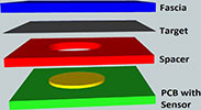
The second easiest implementation is to use a plastic fascia layer with either a silk-screened or vapour-deposited metal flashing for the target. Like the single metal layer design, the plastic fascia provides a surface for the markings, but also provides the elasticity of the button. The metal flashing on the bottom of the plastic layer provides a grounded second plate of the sensor capacitor. See Figure 2 for a stack-up example.
The actuation force is determined by the relationship between button size and any back etching, but relies on the thickness and elasticity of the plastic used. The smaller the button and the thicker the material, the more actuation force is required. However, while stainless steel and aluminium are relatively stiff, plastic is much more flexible than metal. This allows for a thicker fascia and target while retaining the same actuation force. It is also more tolerant of high bending angles, making it relatively immune to denting and permanent deformation.
As with metal, modern silk screen and coating allow a sheet of plastic to look like any surface the designer requires. The surface of the plastic substrate can also be completely or selectively flashed with metal coatings for appearance and markings.
One difference in plastic is the potential problem of maintaining optical clarity in larger thicknesses. Polyester can have problems with clarity, but in the thicknesses typically used for sensor designs this is usually not an issue. Both polycarbonate and polyethylene have good optical clarity. Adhesives can also be found with good optical clarity. Make sure the combination of plastic and adhesive is appropriate to avoid a cloudy or fuzzy appearance.
While water is no longer a major concern with a plastic fascia, abrasion and chemical resistance become more significant. Another potential environmental problem is the dimensional stability of the material over temperature. If the fascia material expands at a significantly different rate than the materials it is bonded to, the adhesive can fail, resulting in false triggers, variable sensitivity and significant sensor-to-sensor crosstalk.
An environmental concern for food preparation and medical markets is the resistance of the material to microbial contamination. Polyester and polycarbonate come with an optional anti-microbial coating, making them a preferred choice for both markets. If the sensor is also going to be exposed to direct sunlight, anti-fogging and resistance to UV yellowing are desirable.
Clear and translucent plastics are the easiest materials to backlight. Not only will plastic pass light, but it will also pipe light along its length, allowing the use of side-light LEDs to backlight the entire surface of the design. If a metallic surface plating is used, then a simple etching process can leave pin-hole openings that mimic the much more expensive backlighting options mentioned for solid metal layers.
Co-moulded metal and plastic
The third option is combining plastic and metal into a single-layer fascia and target. The metal layer is etched or stamped, leaving an empty space around the switches. Plastic is then injection-moulded to fill the gaps. The main advantage of using metal with plastic is it combines the advantages of both.
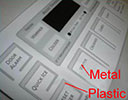
The resulting design enjoys the abrasion resistance of metal, the transparency and translucency of plastic, and an actuation force that is stiffer than plastic, yet softer than metal alone. In fact, the actuation force can be adjusted by varying the ratio of plastic to metal involved in the flex of each button. Figure 3 shows an example of a co-moulded fascia and target layer. The lighter grey material is aluminium and the darker grey is the plastic injection moulded around the sensor.
In a co-moulded design, the actuation force is determined by the same factors as a metal or plastic-only design. The difference is the actual force will be determined by a weighted average of the characteristics of the two materials. This will put the actuation force for the design somewhere between the figures for an all-plastic or all-metal design.
Unfortunately, an exact calculation of the actuation force is heavily dependent on the geometry of the sensor. A useful approximation can be made by using an average of the all-metal and all-plastic calculations. Simply start by calculating the actuation forces of two similar buttons, one made from plastic and the other from metal. Then calculate how much of the button perimeter is plastic and how much is metal, and scale the two actuation force values by the percentage of each in the perimeter of the button.
Taking an average of the two results will give a rough estimate of the actuation force for the co-moulded design. The desired actuation force can then be adjusted by varying the ratio of metal to plastic, and any fine tuning can be made by adjusting the button trip threshold in software.
Sensor appearance is the driving force behind this implementation. The metal provides a good wear resistance and the plastic provides a visual outline for the sensor, as well as a means for backlighting the sensor. Modern silk screens and coatings can create the required look using the same techniques discussed earlier.
Concerns with the effects of abrasion and chemical resistance get more complicated with a composite design. Not only must both the metal and the plastic be appropriate for the intended environment, but the compatibility and adhesion of the plastic with the metal must be considered. For example, if the metal has a higher coefficient of expansion than the plastic, then at extreme low or high temperatures, dust and moisture may leak into the sensor when the metal edge pulls away from the plastic. If the plastic has a higher coefficient of expansion, the plastic may generate stresses that cause the metal to deform at higher temperature, generating a false press.
On backlighting, the plastic provides a means for the light to pass through the metal, both to highlight the button function and to outline the buttons for ease of recognition by the user. Unfortunately, the plastic is often isolated in the design, so it may be necessary for separate locations to be individually lit.
Conclusion
These various sensor design techniques give designers significant freedom in the creation of novel user interfaces. The variety of materials, configurations and techniques can be combined in various configurations to produce truly unique controls from both an aesthetic and ergonomic point of view. However, these techniques are by no means all the possible options and designers are encouraged to think outside the traditional box and talk with their creative third-party design suppliers for additional ideas.
| Email: | [email protected] |
| www: | |
| Articles: | More information and articles about Tempe Technologies |


© Technews Publishing (Pty) Ltd | All Rights Reserved
 printer friendly version