


When measuring temperature, the thermocouple is one of the oldest and most widely used components.
Especially useful in applications that require temperature measurements in hostile environments, such as boilers, ovens, and automotive and petrochemical applications, a thermocouple is capable of measuring temperatures in the range of -200°C to +2500°C. Two of the main advantages of using thermocouples is that they respond more rapidly to changes in temperature than other sensors and are immune to shock and vibration.
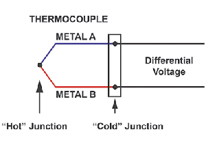
So, what exactly is a thermocouple? A thermocouple consists of two wires made of dissimilar metals, joined together at one end. The joined end is typically referred to as the ‘hot’ junction, while the open end is called the ‘cold’ junction. The differential voltage between the two wires is used to calculate the temperature at the hot junction, as shown in Figure 1.
All thermocouples must measure micro-volt-level signal changes. The most common thermocouple types are J, K and T, and their room-temperature voltages vary at 52 μV/°C, 41 μV/°C and 41 μV/°C, respectively. Because their voltage signal is very small, it can be difficult to extract from the system noise. Also, the thermocouple output is not linear over temperature, requiring the use of high-order equations to accurately calculate the temperature.
Furthermore, a thermocouple measurement is only as accurate as its cold-junction temperature measurement, adding more complexity to an already complex system. Generally, thermo-couple signal conditioning is the largest investment in a thermocouple solution.
Measurement options
The differential voltage generated at the cold junction is dependent on the temperature differential between the hot junction and cold junction. Therefore, in order to obtain an accurate overall temperature reading, one must know the temperature at the cold junction.
This is known as cold-junction compensation (CJC). The overall temperature accuracy of the thermocouple solution is limited by the temperature accuracy of its CJC.
Today, there are many solutions for measuring the cold-junction temperature, such as RTDs, thermistors and silicon-based IC temperature sensors. Thermistors have fast responses and small packages, but they require linearisation and have limited accuracy over wide temperature ranges. They also require current for excitation, which can produce self-heating and increases power consumption, thus limiting their use in many portable or battery-powered applications.
Resistance temperature-detectors (RTDs) are accurate, stable and reasonably linear devices. However, package size and cost restrict their use in many applications. Silicon IC temperature sensors now have temperature accuracies better than 0,5°C. Silicon ICs are simple devices, and require minimal external circuitry or thermal design knowledge to implement. This simplicity, along with improved temperature accuracy, has increased the popularity of these devices in recent years.
Generally, discrete thermocouple solutions use an instrumentation amplifier (INA) to extract the thermocouple voltage, and the INA rejects voltages that are common to each input of the device. Since most of the noise will be common to each thermocouple lead, the INA effectively filters the noise.
There are a variety of instrumentation amplifiers available today. The traditional INA topology utilises two operational amplifiers for the gain stage, which then feed into a third operational amplifier configured as a differential amplifier, as shown in Figure 2.
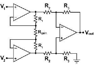
The gain of this circuit is set with a single resistor Rgain. Though this topology can achieve common-mode rejection (CMRR) above 80 dB at DC, the CMRR dramatically degrades as frequency increases. This can be an issue if one of the objectives for this device is to reject high-frequency noise.
There are considerations for using the single-resistor approach. The internal resistors are trimmed to a ratio, rather than an absolute value. Not knowing the absolute value of the internal resistors makes it difficult to determine the gain of the circuit. The temperature coefficients of the monolithic resistors versus the external gain resistor will be different, causing additional gain error over temperature.
Newer architectures sum currents rather than voltages, improving common-mode rejection at higher frequencies. An example of this is Microchip Technology’s MCP6N16, which is shown in Figure 3.
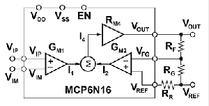
This architecture generates currents that force a voltage across RG equal to the differential voltage from VIP to VIM.
In this circuit Vout = (VIP - VIM)*(1 + RF/RG). Notice that the gain is set using two external resistors, eliminating the previously mentioned concerns with the single-resistor approach.
To summarise, temperature measurement using thermocouple signal conditioning is more complex than that of other systems. The advancement of silicon-based IC temperature sensors and the development of modern INA architectures have addressed many of the historical design challenges associated with thermocouples. Several silicon IC manufacturers have integrated many analog, mixed-signal and temperature sensing devices for CJC, which reduces design complexity and improves overall system performance.
For more information contact Tempe Technologies, +27 (0)11 455 5587, [email protected], www.tempetech.co.za
| Email: | [email protected] |
| www: | |
| Articles: | More information and articles about Tempe Technologies |


© Technews Publishing (Pty) Ltd | All Rights Reserved
 printer friendly version