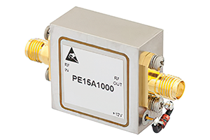
To ensure an LNA design or device performs as designed, there are several ways of evaluating these circuits. Mainly, these measurements are to produce S-parameters, gain, noise figure and linearity figures for a given device.
Low-noise amplifiers (LNAs) are a critical component for telecommunication and sensing systems, as the weak received signals often need to be at a higher signal level for optimal demodulation, digitisation, driving another circuit, or for measurements to be made.

LNAs are also used throughout signal chains to add gain to low-power signals when higher-power signals are needed at the input of other elements within the signal chain. This includes amplifying received signals from an antenna or sensor, or increasing the signal power level from local oscillators (LOs) or other frequency generation/drive circuits where it is necessary to ensure that minimal added noise is contributed.
The main purpose of an LNA is to add gain without adding noise, phase noise or distortion. Generally, LNAs are placed as close as possible to the input signal to minimise exposure of the circuit to noise prior to amplification, as any signal content within the bandwidth of an LNA is amplified. To ensure an LNA design or device performs as designed, there are several ways of evaluating these circuits. Mainly, these measurements are to produce S-parameters, gain, noise figure and linearity figures for a given device.
LNA S-parameter measurements and gain
S-parameter measurements can be made with an LNA that is properly supplied and biased using a vector network analyser (VNA), as LNAs are typically 2-port devices. Hence, only S11, S12, S22 and S21 parameters need to be measured. It is important to note that the S-parameters measured here are generally small-signal parameters, not large-signal parameters, which may be beneficial to measure when characterising LNAs with high gain and relatively high power levels as the load may impact the LNA’s performance substantially.
For low-power LNAs, a VNA measuring the S-parameters may be adequate to provide the gain (S21) if port 1 is the input and port 2 is the output. For higher-power LNAs, a signal generator driving the input port and either a power meter or spectrum analyser measuring the amplified input signal at the output can be used to determine the gain.
LNA linearity measurements
The linearity of an LNA is important to measure, as often the power delivered to receiver circuitry needs to be precisely controlled. The 1 dB compression point (P1dB) can be determined by varying the input power at a given frequency. It can be observed from plotting these measurements that at some point the power in compared to the power out relationship is no longer linear. The P1dB is when the gain (output) deviates by 1 dB from what it would otherwise be if the relationship remained linear.
The other linearity measurement commonly performed on LNAs is the third-order intercept used as a gauge of the intermodulation products produced by an LNA. This is measured by inputting two distinct frequencies at the same amplitude and measuring the input power compared to the third-order intermodulation product produced by the mixing of those two tones (2F1-F2 and 2F2-F1). This measurement is typically performed with a designated frequency spacing between the two tones to provide some point of comparison between LNAs.
LNA noise measurements
Most importantly, an LNA is often chosen for the device’s added noise performance, or noise figure (NF). This is a measure of how much noise an LNA adds to the signal passing through it. This measurement is typically done with a noise figure meter or noise figure analyser, and an RF signal generator. The test system is often calibrated using a calibrated noise source, to remove the uncertainty from the measurement setup and to isolate the noise response of the device under test (DUT). NF is most commonly given in terms of decibels.
Other LNA features of note are:
• Gain flatness.
• Saturation power.
• Port impedance.
• Operating temperature.
• Stability.
• Supply and biasing.
• Electronic and environmental survivability/performance.
• Input and output voltage standing wave ratio (VSWR).
| Tel: | +27 21 555 8400 |
| Email: | [email protected] |
| www: | www.rfdesign.co.za |
| Articles: | More information and articles about RF Design |

© Technews Publishing (Pty) Ltd | All Rights Reserved