Looking at the challenges of a typical IoT rollout, the biggest hurdle usually isn’t how to connect IoT devices to the LAN. Instead, getting power cheaply and reliably to the device is often a far more difficult problem. For example, installing AC power outlets next to every IoT device is laborious and cost prohibitive. It’s also an overkill, considering the relatively low amount of energy required by most IoT endpoints. Therefore, Power over Ethernet (PoE) has become a must-have technology for virtually every enterprise and industrial IoT rollout. That said, PoE installations come with their own set of unique challenges.
Cable professionals, integrators and administrators must possess a certain level of knowledge when it comes to understanding what is needed from a power delivery perspective. Additionally, because PoE standards and use-cases are constantly expanding, deploying and managing PoE endpoints and IoT devices requires a tool that provides granular visibility into whether a PoE device will be able to draw sufficient power across copper cabling for extended periods of time.
Three unique testing phases emerge throughout the lifecycle of the deployment:
1. During new cable installs, when no PoE power sourcing or PoE endpoint devices currently exist to test against, cable installers must use test equipment capable of verifying DC resistance unbalance measurements within a pair and across pairs. This will provide assurance that proper power and data delivery can be achieved over every twisted pair (TP) in the cable run.
2. Once the cabling and PoE switches/midspans are installed, further testing should be performed to verify that the power sourcing equipment is delivering power to PoE endpoints that satisfies the endpoint’s load requirements. In this situation, test equipment acts as the PoE endpoint, and will run power load tests to provide assurance that the required level of PoE at the powered device (PD) can be achieved.
3. PoE load testing is useful to IoT integrators, cable installers, and network administrators, as it helps to eliminate any finger pointing between these groups when a problem does arise. It’s also a great opportunity for the cable installer or integrator to create additional revenue by adding this critical step into their cable plant installation, verification, or device integration process.
One can drill down further to understand the types of PoE tests that should be run, the different types of cabling to choose from based on PoE needs, the importance of cable certification for new installs, and how to choose an AEM test tool based on job role.
How does PoE work and what are the necessary PoE test functions?
According to the IEEE, Power over Ethernet comprises three components: the power sourcing equipment (PSE), the PD, and the cabling used to deliver power to the device. Examples of PSE are the switch or midspan power injector, and an example of a PD is a security camera.
It is important to understand that twisted-pair copper cabling is dual purpose: it not only carries electricity to power the device, but is also used for Ethernet data transport.
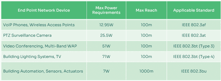
There are several IEEE twisted pair PoE standards that exist today. Each one delivers varying power levels from the PSE to PD. These standards also provide the necessary signalling that both the PSE and PD will understand. The signalling is used to detect whether the PD indeed needs power, and as a negotiation process to determine the amount of power the PD requires for operation. Currently, there are eight different power classes available, as defined by the IEEE. The power delivered by the PSE ranges from 4 W in a class 1 device to 90 W in a class 8 device.
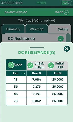
When planning for PoE rollouts, it’s important that both the PSE and cabling be thoroughly tested to verify proper operation within the various PoE classes. This includes not only peak wattage capacity, but also sustained power delivery over time, and whether the cabling can succumb to DC resistance unbalance issues.

Extended testing for DC resistance unbalance has become an essential step within the IoT deployment process, as devices that require PoE++ levels of power at 60 W or higher are more prone to causing significant interference problems with data delivery. Thus, for IoT implementations that require higher power delivery levels such as modern wireless access points and pan, tilt and zoom (PTZ) cameras, thorough testing of DC resistance unbalance is highly recommended.
Finally, both PoE load and negotiation testing will ensure a smooth PoE endpoint rollout, with far fewer issues related to long-term power delivery use and wattage mismatches.
IEEE standards
IEEE standards define different levels of powering. PoE also follows the same distance limitation of 100 m that twisted pair cabling runs follow due to attenuation. This is why the standards define power levels at both the PSE and PD.

Choosing the right cabling
There are several Ethernet cable standards that PoE can operate across. Some cable types are better than others depending on the wattage your PDs require. Within common office and manufacturing deployment environments, one will likely come across existing four-pair copper cabling using CAT5, CAT5e and CAT6 standards. PDs requiring lower wattage can utilise this older cabling. However, it is highly recommended that when powering devices that require 60 W or higher, newer CAT6A (or higher) cabling should be run. These types of cables use thicker conductor diameters that helps reduce resistance. This is critical so that power is not lost due to compounding resistance over longer cable runs.
CAT6A cabling is also better insulated, and can handle the added heat produced by the higher power loads being sent across the wires. This is especially important when running higher wattage PoE in large cabling bundles. Lastly, thicker cables are far more capable of delivering higher power and faster Ethernet transmission speeds for multigigabit connections over twisted pair copper. Thus, running newer cabling future-proofs your IoT investment.
Certify all cabling to ensure it meets stringent standards
To increase the likelihood that cabling won’t be an issue when running PoE, it’s necessary for cabling contractors to certify cabling to meet the cable manufacturer’s strict standards. This is true not only in terms of ensuring that the cabling can operate at multi-gigabit speeds, but also to test and ensure proper power load capacity for IEEE 802.3af, 802.3at and 802.3bt standards.
Choosing the right test tool
Any successful IoT deployment requires that the proper tools be in place to get the job done right the first time. AEM’s product portfolio provides the necessary tools for testing and troubleshooting.
| Tel: | +27 12 349 1341 |
| Email: | [email protected], [email protected] |
| www: | www.lambdatest.co.za |
| Articles: | More information and articles about Lambda Test |

© Technews Publishing (Pty) Ltd | All Rights Reserved