


In principle, selective soldering is similar to other soldering techniques, insofar as three ingredients are required to make a good solder joint: solder, clean metal surfaces to connect, and heat. All three have a big influence on the final result.
The solder’s properties not only define the hole filling, but also have an impact on the appearance and shininess of the solder joint. Heat is required to activate the flux and make the solder flow into the barrels. If there is not enough thermal energy in the assembly, the solder will solidify in the barrel during the process and there may be insufficient hole fill (defined in IPC-A-610E, chapter 7.3.5).
To improve the hole filling properties and to clean the metal surfaces, a flux is applied before soldering. Critical to this process is that the flux is applied at the right place – cleaning the metal and supporting the solder to penetrate into the barrels – and that the flux is activated.
For activation of the flux, a specified temperature must be achieved for a certain duration. These properties are flux specific and should be defined by the maker, since they are most familiar with the ingredients used in the flux chemistry.
Flux residues and potential reliability issues
Although the flux has a similar purpose as in a wave soldering process, selective soldering requires different properties for a flux to be successful. Two of them are essential:
1. Spreading. In selective soldering the flux should not spread too far. Flux is only required in the soldering area and should remain there only.
2. Inert after soldering. Non-activated flux residues are a potential risk for electro-migration.
Since spreading should be limited, it is essential that the mechanism of spreading is well understood. Spreading is not only dependent on the flux properties, but also influenced by the board material and other factors.
Surface energy
Among the factors that influence flux spread are flux surface tension (flux type), surface energy of the board (solder mask), temperature of the flux, and temperature of the board.
In Figure 1 the impact of the solder mask is visualised. For wave soldering, a board with a high surface energy (>50 mN/m) is preferred. This makes the flux spread to all areas and thus eliminates the risk for open solder joints, bridging, spikes and webbing. Due to the good spreading the residues will be less visible, which is a cosmetic advantage.
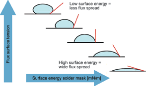
For selective soldering applications a lower surface energy of the board is desired; a typical value for good spreading is ~35 mN/m. One should be aware that heating processes before selective soldering (like reflow soldering) may have an effect on the surface energy of the solder mask.
Preheated board
One method to minimise flux spread is to preheat the assembly before applying the flux. As an experiment to visualise the impact of a hot surface, flux spread can be observed clearly on bare copper material for three different fluxes. For this comparison one typical alcohol, one low-VOC and one VOC-free water based flux are selected.
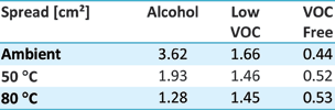
Table 1 shows the spreading area and Table 2 the amount of dry flux per square centimetre. The amount of flux that was dropped on a copper coupon was 10 μl. This was repeated at ambient temperature, and with the coupons preheated to 50°C and then 80°C.
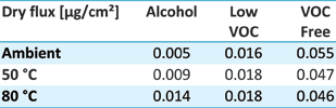
To summarise the major observable differences:
1. An alcohol flux will spread less when the board is preheated, whereas a VOC-free, water-based flux will spread more when the surface is hot.
2. Owing to minor spreading, the solid content left per cm² is much more for a VOC-free flux than for an alcohol based one.
Since alcohol fluxes are safe, the trend for selective soldering fluxes pushes in the direction of alcohol based fluxes with a higher solid content to have enough activity per square centimetre.
Satellite-free dropjet
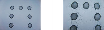
Dropjet fluxing has become the application method of choice to apply very small amounts of flux with very high accuracy. As in inkjet technology, during the jetting process satellites are formed due to the nature of the liquid and jetting method. These satellites take the form of very small droplets when spraying begins – called head satellites – and at such time as the plunger closes – called tail satellites.
Many studies have been done using high-speed cameras to understand the formation and behaviour of these flux satellites. Since their size and direction are not controllable, these flux particles may be deposited in unwanted SMD areas and are a potential reliability risk. Satellite drops, which often follow each fast-moving main drop ejected from the nozzle, are undesirable because they are far more readily misdirected by aerodynamic and electrostatic forces.
To eliminate the occurrence of satellites, a new HF (high-frequency) dropjet has been developed with a sapphire orifice and an internal pressure compensation bladder. This results in the droplets retaining their integrity longer and travelling further.
A way to visualise flux patterns is by fluxing on fax (heat sensitive) paper. To illustrate the satellites and the difference between an HF satellite-free and a common dropjet, Figure 2 shows flux sprayed on fax paper using the same settings.
Spreading experiment
To define the spreading of flux (alcohol based with 3,3% solids) in Vitronics Soltec’s mySelective soldering applications, a Box-Behnken experiment is fit to purpose. In this experiment the three different parameters of the dropjet flux system are set at two different levels. These parameters are:
• Open time dropjet (500 – 2500 ms).
• Frequency dropjet (10 – 300 Hz).
• Speed of the flux robot (10 – 150 mm/s).
When conducted over 15 runs on a mySelective 6748 using the traditional dropjet nozzle, with flux applied on a typical wave soldering board and on a board with a modified solder mask, the results in Table 3 are produced.
![Table 3. Experimental settings for flux width [mm] and the calculated dry flux amount [μg/in²].](articles/Dataweek - Published by Technews/k2117f.png)
In the first column the width of the flux stroke is listed. It is obvious that for the solder mask with a surface energy of 35 mN/m (modified for selective soldering) spreading is better under control. The process window is wider; the width of flux can be varied between 2 and 10 mm with the settings in the experiment. For the board with the higher surface energy, the flux spreads up to 16 mm and it is difficult to apply a small stroke of flux. For successful soldering, a flux amount between 500 – 2000 μg/in² is required.
In the second column the flux amount is calculated (flow measured with a flux flowmeter). The red values are out of spec. Due to spreading, only three settings for the second board are acceptable for soldering, which makes it hard to find the sweet spot for a successful process.
The most important conclusion to take from this experiment is that boards designed for wave soldering with a higher surface energy are not suitable for a selective soldering application.
Nitrogen/inert soldering area
As temperatures rise, flux materials undergo changes in their physical and chemical properties. These include the evaporation of volatile fractions, their surface activity and their melt viscosity. The consequence for the solder flux is early displacement by the scrubbing action of the solder, and ultimately the thermal breakdown of the material. This results in loss of its functionality as a protective blanket, and the loss of an insulating film over the liquid solder when it wicks up the barrel of the via or through-hole.
To successfully selective solder with a small amount of flux, it is essential that the environment is inert during soldering. Nitrogen coverage of the solder enables good penetration even with less flux activation. The lack of oxides reduces bridging and the solder joints also become shinier when there is a good nitrogen blanket.
Soldering performance with minimal flux
To determine the least amount of flux to apply while maintaining a consistent and robust selective dip soldering process for an automotive application, let us consider a relative variation in flux as shown in Table 4, with Level 2 being the most appropriate for a modern manufacturing line.
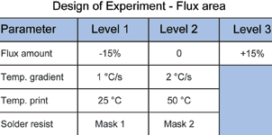
The variables in this experiment include the solder mask, print temperature during fluxing, and preheating gradient. As shown previously, the print temperature influences spreading of the applied flux. In this experiment a low-VOC flux was used that contained 20% water in combination with alcohol.
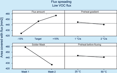
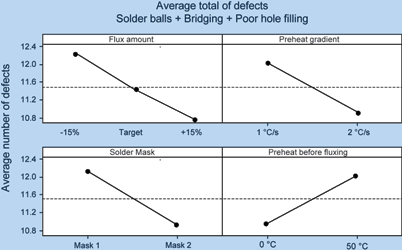
The flux was applied to the board using these settings. After preheating the board was taken out of the selective solder machine and the components removed. The board was scanned and the spreading analysed using a software program. Under the same conditions, boards were soldered to verify solder quality at the three settings, with the objective of achieving good solder performance with the least amount of flux.
As Figure 5 shows, more flux equals better soldering. The solder mask has a significant impact where faster preheating is preferred and fluxing a hot board does not return acceptable soldering results.
For a defined combination of flux and solder mask, it is possible to develop a mathematical formula for the spreading. Since the surface tension of the solder mask is such a vital factor, there is no generic flux formula; rather, one must be derived with respect to the solder mask type. This formula can then be imported via an external software package to program the selective soldering machine off-line.
Conclusions
Flux plays a critical role in the selective soldering process, regardless of the technique used – dip or drag, horizontal or tilted, wettable or non-wettable nozzles.
The interaction between flux and solder mask defines the spreading, the amount of dry flux solids per area, and therefore the solder quality. It is better for soldering and reliability to have an alcohol flux with higher solid content that leaves more sticky residues than the use of an organic type of flux.
Transparent flux residues may look nice, but unprotected activators are a potential risk in the field.
| Tel: | +27 11 609 1244 |
| Email: | [email protected] |
| www: | www.zetech.co.za |
| Articles: | More information and articles about ZETECH ONE |


© Technews Publishing (Pty) Ltd | All Rights Reserved
 printer friendly version