


It’s easy when commissioning or simply plugging a battery into the device it is destined for, to overlook all the steps that went into its production. Often the minerals that are used in making a battery are mined in one country and processed in another, for example, and by the time it leaves the factory it will have undergone numerous quality checks. Just as it can be enlightening to know where our food comes from (and some people insist on knowing), understanding what goes into making a sealed lead-acid (SLA) battery can provide assurance that it was created with care, and confidence that it can be trusted to power its application reliably.
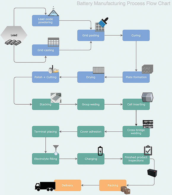
The manufacturing process of an SLA battery can be broadly divided into the following stages: oxide and grid production; pasting and curing; plate formation; assembly; electrolyte filling; charge-discharge process;, finished product inspection; packing and dispatch.
Oxide and grid production
First of all, a lead ingot is ground into lead powder and gets oxidised, then mixed with the alloy additive. This is the basic material that makes up the battery pastes. To make a grid it needs to be cast, which is done by melting the material in a melting pot, and then pouring this molten lead into the patterns of the battery grid. By contrast, when a stamping operation is used, the battery grids are made by stamping them from lead sheets. Once these grids have cooled after casting, they are passed to a trimming machine to trim the rough edges and casting gates.
Plate production
There are several steps involves in producing the battery plates. These include pasting, curing, plate formation, drying, polishing and cutting.
Pasting is probably the most important aspect because the material and formula of the paste is a top secret to the battery’s manufacturer. The paste contains the active material for the grid and is the essential ingredient in creating a reaction in the cell.
These pastes are used to fill the positive and negative grids, but they are not all the same. Depending on the design, they can be made up of different chemical compounds mixed in different proportions to generate the active materials for the battery cell. These pastes are then forced on the interstices of the grids to make the pasted plates. These pasted plates will be cured in ovens under controlled conditions of temperature and humidity, after which they are allowed to dry at ambient temperatures.
The next step is plate formation, whereby the plates are dipped into the sulphuric acid mixer and then charged by using a rectifier. This process continues for around 16 to 24 hours. After that, the plates are moved into the wash tank, then sent to an oven for drying.
The final production step the plates need to go through is the polish and cutting process. after which they are ready for assembly.
Assembling and filling
In this stage, all the component parts – plates, separators, cover, safety valves, O-rings and terminals – are assembled into a battery case and then sealed. This in turn requires several steps such as plate stacking, insertion of separators, group welding, cell insertion, cross-bridge welding (inter-cell connector and plate connecting), cover sealing, terminal placing and electrolyte filling.
In the stacking step, positive and negative plates are strapped to a suitable rack, stacked together and a separator is inserted in between them. The common type of separator used in an SLA battery is AGM (absorbent glass mat) which is a glass mat specially designed to wick the battery electrolyte between the battery plates.
The purpose of the welding process is to collect the stack of plates and separators to form a solid group; these elements are then inserted into the battery cells and welded to the respective positive and negative posts on the battery’s case top.
Following that, what remains to be done is to place the terminals and weld the poles, and then put on the cover to seal the battery. At this stage the only thing still to be done to complete the assembly process is to fill the battery with electrolyte, then send it for the first charge of its life.
Charging, inspection and packing
A battery’s charging process must be carefully controlled, and may require 36 to 48 hours depending on its size. A low charging rate is generally employed such that the battery will be discharged and recharged several times to attain the best working conditions.
After charging and discharging, the battery will be set aside for 5 to 7 days, during which it will undergo several inspections and tests by specialised instruments. Before it can be sent for packaging, it also needs to pass a capacity test, OCV interior resistance test and high rate discharge test to rule out any defects.
Finally, the battery is now ready to be packaged, shipped and delivered to the customer to install and commission it in preparation for a long and productive life in its intended application.
For more information contact Forbatt SA, +27 (0)11 469 3598, [email protected], www.forbatt.co


© Technews Publishing (Pty) Ltd | All Rights Reserved
 printer friendly version