


Mary Tamar Tan from Microchip Technology explains how a real-time clock and calendar module can reduce component count and cut programming costs in smart meters and other applications.
Reducing both the component count and user programming costs are goals in almost any design. Both of these desires can be addressed by using a real-time clock and calendar (RTCC) module that provides accurate time and date keeping and is optimised for low power usage with little or no intervention from the CPU. This can provide benefits in applications such as digital alarm clocks and smart energy meters, something becoming increasingly important as more and more countries role out smart grids.
Available with Microchip PIC microcontrollers, the module is a 100-year clock and calendar with automatic leap year detection. The range goes from the first second of 1 January 2000 until a second before midnight on 31 December 2099 and uses the 24-hour rather than the AM and PM 12-hour format, with visibility down to 0,5 s.
The alarm is configurable for 0,5, 1 and 10 s, 1, 10 and 60 min, or day, week and month. Figure 1 shows the block diagram of the module. It uses a separate clock source coming from an external crystal oscillating at 32,768 kHz from the secondary oscillator (SOSC) of the T1OSC for some devices. This lets the module continue running even when the CPU clock is disabled during deep sleep mode.
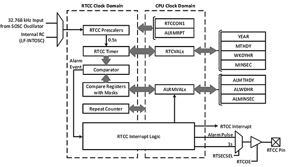
The 1:16384 clock prescaler provides the 0,5 s visibility to the user, which in turn allows the RTCC timer to increment the appropriate second, minute, hour, day, month and year values stored in the RTCVALx registers. These values are compared with the user-set alarm values to trigger an alarm interrupt whenever a match occurs.
The alarm values are stored in the ALRMVALx registers. Alarm masks are used to set the time interval between each alarm event if multiple periodic alarms are needed. The RTCC pin can output either the seconds clock or an alarm pulse at half the frequency of the alarm, depending on the configured settings. To simplify the firmware, the register interface for the RTCC and alarm values are implemented using binary coded decimal (BCD) format.
Peripheral configuration
The user configures the time by writing the required year, month, day, hour, minutes and seconds to the timer registers. However, the RTCC enable bit (RTCEN) and the RTCVALH and RETCVALL registers can only be written to when the RTCC value registers write enable bit (RTCWREN) is set to one, otherwise any write to these registers will be ignored. The RTCC timer (RTCVALx) and alarm timer (ALRMVALx) registers can only be accessed through corresponding register pointers. Every write or read to the RTCVALH register decrements the RTCC pointer value by one until it reaches 00.
When the RTCC output pin is enabled, the user can choose either to output the seconds clock or an alarm pulse, operating at half the frequency of the alarm. For more accurate timing and to ensure uninterrupted operation of the RTCC even in deep sleep, the SOSC is recommended as the peripheral’s clock source. Once the RTCC is enabled, the timer proceeds with the count from the configured starting point. Also, to avoid accidental writes to the RTCC timer register, it is advised that the RTWREN bit be cleared when not writing to the register.
The alarm feature is configurable from half a second to one year and can be repeated as desired by the user. Every read or write to the ALRMVALH register decrements the alarm pointer value by one.
Battery backup mode
A feature of the RTCC module is its ability to continue operating from a backup battery if there is a power loss that would otherwise affect its timing accuracy. This is VBAT mode, and the PIC microcontrollers have both MCU power reduction and uninterrupted operation of the RTCC through the VBAT hardware-based power mode. This mode uses a backup power source connected to the VBAT pin as shown in Figure 2.
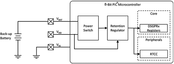
An on-chip power switch detects the power loss from the VDD and connects the VBAT pin to the retention regulator. This provides power at 1,2 V to maintain the retention regulator, as well as the RTCC, with its clock source if enabled and the deep sleep general purpose registers (DSPGPRx). The RTCC continues to operate as if there was no power interruption.
The device automatically wakes from VBAT mode once VDD is restored. Wake up from this mode is identified by checking the state of the VBAT bit. If this is set when the device is awake and starting to execute the code from the reset vector, it indicates that the exit was from VBAT mode. To identify future VBAT wake-up events, the bit must be cleared in software.
One of the Microchip demonstration boards that supports the VBAT operation is the LCD Explorer demonstration board. It is provided with a battery holder for a CR2032 3V button cell.
Digital alarm clocks
Figure 3 shows a sample implementation of the RTCC with the LCD driver and the capture-compare-PWM (CCP) modules for a digital alarm clock application.
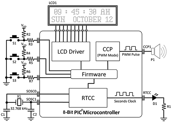
The SOSC provides the clock for the RTCC module. If the RTCC pin is configured to output the seconds clock, this allows LED D1 to blink once every second. The values in the RTCVALx registers are manipulated by firmware to be displayed on LCD1 through the LCD driver module.
The alarm interrupt triggers the CCP module to generate a pulse-width modulated output that activates the P1 piezo buzzer on every alarm event. The duration of the alarm is controlled through firmware.
The S1, S2 and S3 pushbutton switches are used to set the initial RTCC time and date as well as the alarm settings. One of the buttons can also be used to trigger the start of the RTCC count.
There are several Microchip demonstration boards that can be used for this application. Several PIC microcontrollers with the RTCC module also have an internal LCD driver module that can directly drive the LCD glass while others can use the MSSP module to communicate with the LCD while displaying the time and date.
Energy meters
In an energy metering device, the RTCC module can be integrated with other peripherals such as the analog-to-digital converter (ADC) and LCD driver modules. MCUs for metering applications should have a high-resolution ADC for voltage and current measurements, must consume low power, be able to operate from a battery to maintain uninterrupted operation of the RTCC, and have an EEPROM for data logging and storage of calibration data. Microchip has a number of 8-bit PIC microcontrollers that meet these requirements.
The periodic auto-adjust feature in the RTCC module can be used with the ADC module to perform software temperature compensation for a more accurate time. These microcontrollers also have a built-in LCD module that can directly drive an LCD to show the real-time energy consumption. And they have an external interface for a battery source through the VBAT pin, which lets the RTCC run continuously during a power loss.
Conclusion
The RTCC modules of PIC microcontrollers provide the necessary features to maintain accurate time and date keeping. They are easy to configure, provide automatic error calibration and have very low power consumption. Since the RTCC is usually not implemented by itself, its usefulness is better appreciated when integrated with other peripherals. PIC microcontrollers provide versatile choices of peripherals that can be implemented with the RTCC module for digital alarm clocks, energy meters and other applications.
| Email: | [email protected] |
| www: | |
| Articles: | More information and articles about Tempe Technologies |


© Technews Publishing (Pty) Ltd | All Rights Reserved
 printer friendly version