

MEMS-based accelerometers are increasingly deployed in harsh environments where mechanical stress is not just expected, but constant. Two critical specifications often found in accelerometer data sheets are shock survivability and vibration tolerance. While they may appear similar, they serve distinct purposes and are tested differently. Understanding these differences is essential for selecting the right sensor for your application.
Shock survivability: Withstanding the unexpected
Shock survivability refers to an accelerometer’s ability to endure nonrepetitive, high magnitude acceleration events. These events typically occur during the component (IC) handling, assembly, or accidental drops.
• Test standard: IEC 60068-2-27.
• Test method: Half-sine wave pulses of defined magnitude and duration, applied across all axes.
• Purpose: Ensures the device remains functional after rare but extreme shocks.
• Failure mechanism: Typically results in gross failures such as beam breakage in the MEMS structure, but can also include system-level issues like wire bond detachment or die cracking.
Vibration tolerance: Surviving the everyday
Vibration tolerance, in contrast, measures the sensor’s ability to function reliably under continuous or repetitive vibrations – a common condition in many industrial and transportation applications.
• Test standard: usually MIL-STD-883 Method 2007 (or manufacturer-defined).
• Test method: Continuous random vibration within a specified amplitude and frequency range.
• Purpose: Validates long-term reliability under operational vibration.
• Failure mechanism: Often leads to stiction or particle contamination due to the wear of protective mechanisms.
Why the distinction matters
Shock and vibration stress the sensor in fundamentally different ways. A sensor rated at thousands of g’s shock survivability may fail under hundreds of g’s continuous vibration. This distinction is crucial for ensuring both sensor survival and performance. Shock survivability refers to nonrepetitive extremely high magnitude impacts that can result in system-level failure, whereas vibration tolerance refers to long-term reliability.
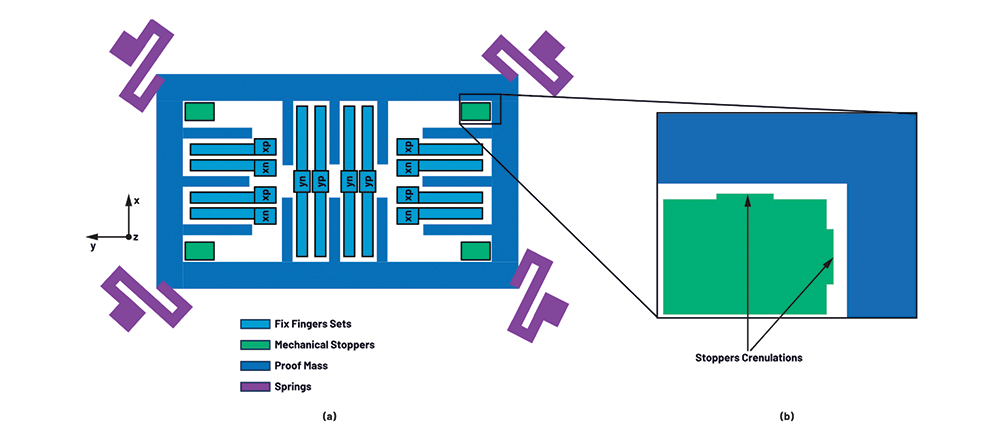
The MEMS sensor design plays a key role in defining the tolerances for both metrics, shock and vibration. For example, mechanical stoppers and anti-stiction coating materials are some of the measures used in the design to protect the MEMS structure integrity. The anti-stiction coat creates a low surface energy and/or electrical insulation, whereas the mechanical stoppers prevent the proof mass from making full contact with the fixed fingers set. Figure 1. shows a simplified representation of a MEMS accelerometer. The mechanical stoppers usually have 4&nsp;μm to 5 μm wide crenulations (small bumps) that reduce the contact area under high shock events, which helps avoid stiction.
Consider heavy machinery, like a dozer, where accelerometers are used as tilt sensors for proper operation on uneven terrain or for terrain levelling. In this application, the accelerometers may experience continuous random vibration in the tens of g’s
An accelerometer like the ADXL357B is the perfect candidate in terms of performance. Even though its full-scale range is limited to ±40 g, it can withstand larger vibrations. The vibration safe zone is highly dependent on the sensor’s mechanical design, including its resonant frequency, damping, and the acceleration input required to hit the mechanical stoppers
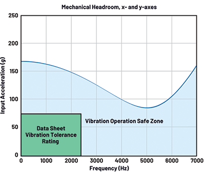
This helps engineers understand how much margin exists before the proof mass hits the stoppers, and how the sensor resonant frequency and quality factor play a role in it. As the input vibration gets mechanically amplified by the quality factor, the closer the vibration frequency is to the sensor resonance, effectively reducing the mechanical headroom.
Electrical bandwidth and mechanical limits
Accelerometers usually have analogue and digital filters on their built-in signal chain, and newer sensors, like the ADXL380, even have a digital equaliser filter, effectively extending its bandwidth flatness up to 4 kHz. This is useful for applications like road noise cancellation (RNC), where accurate detection of broadband vibrations is critical for generating effective anti-noise signals. However, it is important to note that electrical filtering or equalisation does not eliminate the physical excitation of the MEMS structure. The sensor still experiences mechanical stress, and operating beyond its mechanical headroom can result in stiction, fatigue, or structural degradation. Designers must ensure that vibration amplitudes remain within safe mechanical limits, even if the electrical output appears linear across the extended bandwidth.
Shock vs sensor full-scale range
It is worth noting that the ADXL357B (±40 g range) and the ADXL380 (up to ±16 g range) have the same survivability rating as a ±400 g range sensor like the ADXL373, which is 10 000 g peak amplitude, 0,1 ms pulse width half-sine wave shock profile. However, the ADXL373 has a much higher vibration mechanical headroom. The shock tolerance rating can be seen as a system-level test. Not only is the MEMS sensor put under test, but also the integrity of wire bonds, die attach, package, and even solder joints need to withstand this test. These MEMS sensors from ADI might be able to survive repeated shocks even higher than 10 000 g without structural failure, but it might not be the case for other parts of the system that form part of the device.
Shock testing
Replicating standardised shock tests in-house is often challenging due to the need for specialised equipment such as drop towers or shock tables that can be several meters tall and precisely controlled. As a result, engineers frequently seek practical alternatives. One common approach is to reduce the peak acceleration while increasing the pulse duration, maintaining equivalent shock energy. This is based on the principle that the area under the acceleration-time curve (velocity) is a key indicator of shock, as it correlates with the impact energy. For a half-sine shock pulse severity, the impact velocity can be estimated using Equation 1:

where V is velocity in m/s, A is peak acceleration in m/s2, and D is pulse duration in milliseconds. For example, both a 200 g shock lasting 3 ms and a 3000 g shock lasting 0,2 ms result in an impact velocity of approximately 3,8 m/s, as specified in IEC 60068-2-27. This equivalence allows for more accessible test setups, while still approximating the mechanical energy of a standard shock event.
Conclusion
Shock survivability and vibration tolerance are often misunderstood as interchangeable specifications, yet they represent fundamentally different stress profiles and failure mechanisms in MEMS accelerometers. Shock events are rare but intense, requiring robust mechanical design to prevent catastrophic damage, while vibration is persistent and insidious, demanding long-term reliability and resistance to wear.
Understanding these distinctions is critical for engineers selecting sensors for harsh environments. By considering factors such as mechanical headroom, damping, and system-level robustness, designers can ensure that the chosen sensor, not only survives, but performs reliably over time.
Ultimately, matching the sensor’s specifications to the application’s mechanical stress profile is essential for achieving both durability and precision. With the right sensor and a clear understanding of its limitations and strengths, engineers can confidently deploy MEMS technology in even the most extreme conditions.
| Tel: | +27 11 923 9600 |
| Email: | info@arrow.altech.co.za |
| www: | www.altronarrow.com |
| Articles: | More information and articles about Altron Arrow |






© Technews Publishing (Pty) Ltd | All Rights Reserved
 printer friendly version