


The main source of heat in electronic equipment is their semiconductor chips, and the temperature sensitivities of these chips present a challenge in de-signing cooling mechanisms. Overheating causes the chips to fail prematurely – and failure of only one chip can disable the entire equipment. The higher the chip temperature, the earlier and more certain the failure.
The main source of heat in electronic equipment is their semiconductor chips, and the temperature sensitivities of these chips present a challenge in designing cooling mechanisms. Overheating causes the chips to fail prematurely – and failure of only one chip can disable the entire equipment. The higher the chip temperature, the earlier and more certain the failure.
As functionality has increased, the associated heat dissipation has escalated to the extent that it is recognised as a potential limitation on the pace of electronics development. Appropriate cooling strategies are needed to prevent overheating, and failure, of critical components.
In electronics, the complete design cycle from concept to first customer ship is much shorter than in traditional manufacturing industries – in some sectors, now as short as nine months – and delays in product release of even a few weeks can severely affect profit.
Electronics cooling design and simulation applications have to be quick, reliable and integrated into a fast-moving, complex design process. The people responsible are not experts in CFD or fluid dynamics, and they do not want to spend a lot of time learning detailed CFD concepts, or running potentially time-consuming operations such as sophisticated grid generation.
Mechanical engineers are responsible for all aspects of the physical design of the equipment, that is, everything beyond the electronics design, which typically culminates in the printed circuit board (PCB) layout. They are responsible for the enclosure, appropriate location of the PCBs and other components, and for ensuring structural integrity as well as safe, reliable operation of the equipment. Cooling and thermal design is only one of the issues they are concerned with, although often it is a crucial issue.
Mechanical engineers have to collaborate with electronic designers using electronic design automation (EDA) software and with other mechanical designers using mechanical design automation (MDA) software. Thermal design software is expected to contribute at all stages of the design process, from concept, through design exploration and optimisation, to final verification.
These diverse needs have major implications for software development, especially with regard to interface, data management and integration.
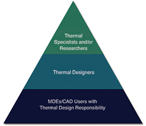
Traditionally, CFD-based thermal design software has targeted engineering analysts with specialised knowledge of thermal design and the use of CFD techniques. These engineers still form a core group in electronics companies today; however, CFD-based thermal design has broadened to include electrical engineers, general mechanical design engineers, industrial designers and marketing engineers (Figure 1).
As a result, the requirements for designing a software solution have become more challenging in terms of user interface (UI) design, geometry and attribute pre-processing, interoperability with other mechanical computer-aided design (MCAD), CAE and EDA software, obfuscation of CFD terminology and functionality, post-processing results and meshing/solver performance.
General-purpose CFD software is far from ideal in satisfying these requirements, which is why special-purpose software, such as Mentor Graphics FloTHERM XT, optimised for electronics thermal applications, with industry-specific input and control, was developed.
Thermal design issues
Inside electronics equipment is a complex assembly of many solid objects (such as PCBs, electronics packages and devices, cabling, fans and heatsinks). Air flow is confined within narrow regions between these solid objects. As well as convective transport within the air, conduction within the solid objects (which can have extremely complex internal structures) is critical. Analyses involve large numbers of such objects (sometimes thousands), as well as extreme disparities in scale (from metres to micron scale).
Because of this complexity, electronics products pose a unique set of challenges for thermal simulation, including geometry capture, scale disparity, uncertainty over missing data (component thermal data, power dissipation, material properties, layer thicknesses, interface resistances), transitional flow regime, mesh generation, hardware environment, and the need for increased accuracy.
Geometry capture
During detailed design, the geometry comes from both the EDA and MDA design flows. One particular challenge is that EDA systems deal with 2D representations of the electronics because both IC and PCB design are done using schematics. PCB design tools require only the component layout and often do not contain even the most basic geometric information about the components, such as component height. Detailed information about the internal geometry of the chip packages is typically unavailable.
Scale disparity
Miniaturisation resulting from Moore’s Law has caused an increasing disparity of length scales, between the size of the physical product and the size of the internal components and circuitry. Typically metre to micron scale geometry has to be accommodated within the same model. The presence of small gaps, in the casing for example, can also have a profound effect on the cooling of the electronics.
As a result, scale disparity continues to increase over time – this results in the requirement for behavioural models when the geometry cannot be represented directly within the simulation, as is usually the case with PCB traces on multilayer PCBs, and compact thermal models (CTMs) for IC packages to avoid having to model the internal geometry, which is often unknown.
Missing data
This leads to another challenge unique to electronics cooling applications – missing data. Material property data is absent from MCAD systems, so CFD simulations in general suffer from this problem. In the case of electronics cooling applications, systems are essentially constructed from many components from many different suppliers, the thermal characteristics of which are typically not well understood. These include IC packages, PCBs, heat pipes, fans, Peltier devices, etc.
The geometry comes in part from the EDA system, which often does not include any information on the materials being used. This adds complications during electronic systems assembly where thermal interface materials (TIMs) and gap pads are used to maximise the thermal contact between different parts of the system to implement an effective cooling solution.
Also, operational power information is needed for the active components to predict system temperatures under operational conditions, which vary as a function of the product’s usage. Design for steady-state operation at maximum power, which leads to significant over-design, is no longer tolerable. Increasingly, transient simulations are needed to ensure reliable operation and minimise overdesign.
Flow regime
In highly cluttered electronic systems, air is forced through channels that contain all manner of protuberances that induce low Reynolds Number transitional flow. However, this wall-induced turbulence is not self-sustaining, and the flow would be laminar if the channel were smooth. Turbulence modelling is, therefore, a particular challenge. Within a fast-paced design environment, providing a sufficiently fine mesh to perform large eddy simulation (LES) is completely impractical because of the large number of flow channels, objects, etc. combined with a large system residence time.
Until recently, the practicality of using standard two-equation Reynolds Averaged Navier-Stokes (RANS) models has been questionable. Zero-equation ‘effective viscosity’ models have been favoured to impose an estimated turbulent viscosity because the low mesh densities often used would cause one- and two-equation models to predict less realistic turbulent viscosity values than can be estimated based on empirical data and knowledge of the bulk flow velocity.
A key issue with one- and two-equation models is the need to refine the mesh near to the surface when used with standard, generalised and scalable wall function treatments (log law, van Driest, 1/7th Power Law, etc.), to provide a y+ value of roughly 30 for the near wall cell, with a low mesh size inflation rate out to the core flow.
In electronics applications, boundary layers start at the leading edge of components, PCBs, heatsink fins, etc. resulting in a large number of very thin boundary layers to resolve within the system, so the standard advice on y+ simply cannot be followed. Consequently, LVEL remains the model of choice. However, the recent application of immersed boundary treatments to electronics cooling applications overcomes this drawback.
Mesh generation
Although generic to CFD, mesh generation for electronics cooling applications presents a challenge because of the sheer number of solid–fluid and solid–solid surfaces that need to be captured. As a consequence of the need for fully automated optimisation including geometry changes, the meshing also must be fully automated with no manual intervention beyond predefining the required mesh sizes before meshing is started.
A fortuitous outcome of using EDA systems to design components and PCBs in 2D, with no aesthetic requirements for the unpackaged electronics, is that electronics tend to contain large numbers of Cartesian-aligned objects, so Cartesian-based grid systems are the natural choice for this application. However, size constraints are forcing electronics designers to angle components on boards, insert DIMMs at an angle, and design heatsinks with non-Cartesian profiles.
Use of simple Cartesian meshes with grid lines that ‘bleed’ out from an object to the edges of the solution domain are inadequate because they quickly lead to unacceptable mesh counts when increasing geometric detail is added to the model. As a result, the use of locally refined Cartesian overset grids to refine the mesh within and around objects has become prevalent, allowing either porosity or voxelisation treatments to approximate non-Cartesian and non-aligned Cartesian objects with acceptable accuracy in many cases.
As the amount of non-Cartesian geometry present within electronics systems has increased, so has the need for more sophisticated meshing strategies. Over recent years, Octree meshes with MCAD-embedded CFD in early product design have increasingly been used across a range of industries and applications where the product design process is built on a company’s MCAD system.
In electronics, design processes vary considerably from company to company. Embedding CFD within the MCAD system may not facilitate its use because often much of the early design work will be done outside the MCAD environment, and the design process may be centred on the company’s EDA flow. Thus, the simulation approach used in MCAD-embedded CFD needs to be available within a standalone product.
Hardware environment
Traditionally, thermal design has been done alongside electronic design. The use of high-performance computing (HPC) infrastructure for CFD has been far less than in other industry sectors; for example, in automotive, HPC has facilitated the use of LES to undertake ‘high fidelity’ CFD to address difficult aspects of the product design, such as aero-acoustics. But in electronics cooling applications, increased simulation precision does not translate into improved product quality. The quality of the simulation model is limited by far greater uncertainty in the input data.
To date, good scalar performance with reasonable scaling up to 8-16 cores has matched market requirements. Good scaling for a limited number of shared memory nodes is likely to remain the target for hardware performance. The hardware environment may change away from desktop to cloud-based computing, which will greatly facilitate design space exploration by the use of numerical design of experiment techniques.
Increased accuracy
As a consequence of design margins shrinking, the need for simulation accuracy is increasing. This, however, does not translate directly into a need for higher-fidelity CFD. Indeed, since the early 2000s, clock speeds have not increased, capping die-level power density, and power increases have occurred at higher levels of packaging, such as the PCB.
What has this to do with accuracy? The allowable temperature rise from ambient to junction is not increasing, but as power densities increase within the package, PCB, etc., the proportion of the temperature rise that occurs in the air is diminishing.
Put another way, the importance of modelling the conduction within the solid structures is increasing. This explains the emphasis placed on MCAD integration (e.g. for heatsink design), and perhaps more importantly EDA integration, to accurately capture the copper content and distribution on PCBs, effects such as Joule heating in traces, and power and ground planes, and to accurately measure the thermal conductivity of TIM materials, particularly the softer Type I and Type II materials that are not well suited to being measured in ASTM D5470–based equipment.
Solving thermal design challenges
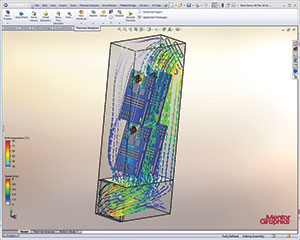
The electronics-cooling CFD software, FloTHERM XT, has been created to address these challenges. FloTHERM XT provides easier modelling of more complex devices and enclosures, connected with SmartPart technology where required, particularly for LED lighting, consumer electronics, aerospace/ defence and automotive design engineers.
Meshing can take up a significant amount of time and energy in some general-purpose CFD codes and can be a cause of frustration when it goes wrong. Most general mechanical engineers would like to simply have the software do the job for them wherever possible, but with the ability to switch to more manual definition should the need arise, and this has reinforced the need for more sophisticated meshing strategies. The advanced code in FloTHERM XT provides semi-automatic, object-based algorithms, with options to adjust the mesh manually where necessary or to allow the freedom and control that is required by the more experienced, and CFD-aware, thermal engineers.
FloTHERM XT uses highly stable numerical schemes and solution controls that operate semi-automatically to control the convergence of the solution with only the minimum of intervention ever being required.
For electronics cooling applications, issues relating to turbulence modelling are rarely, if ever, the largest source of error in the results. It is more likely to be uncertainties in power dissipation, materials, flow rates or interface resistances. However, turbulence can be a source of concern for some more specialised designs.
The FloTHERM XT CFD solution provides the best possible model for the application area of interest and only provides alternatives if there is a clear reason to do so. The software provides options for laminar, transitional and turbulent flows, but limits the turbulence models that are available to avoid confusion.
FloTHERM XT makes use of a general two-equation model combined with a proprietary immersed boundary treatment for near-wall effects that smoothly transitions between the different flow regimes, resulting in excellent benchmark results appropriate for electronics applications.
Editor’s note: For a full description of the capabilities and features of FloTHERM XT, as well as a case study demonstrating the software in action, readers can access the full white paper at www.dataweek.co.za/papers/k4893.pdf.
For more information contact ASIC Design Services, +27 11 315 8316, [email protected], www.asic.co.za
| Tel: | +27 11 315 8316 |
| Fax: | +27 11 315 1711 |
| Email: | [email protected] |
| www: | www.asic.co.za |
| Articles: | More information and articles about ASIC Design Services |


© Technews Publishing (Pty) Ltd | All Rights Reserved
 printer friendly version