Often in applications with keypads, the condition can occur where a key can be held or stuck down, causing excess current consumption and reducing the battery life of a battery-operated product.
This article shows a solution. The keypad interface here, based on the Texas Instruments' MSP430, draws 0,1 µA while waiting for a key press, is completely interrupt driven, requiring no polling, and consumes a maximum of only 2 µA at 3 V if all keys are pressed and held simultaneously.

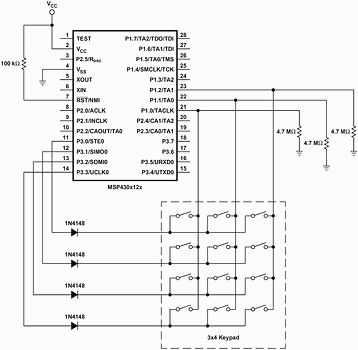
The keypad interface described in this article (schematic in Figure 1) is based on MSP430F12x device from. Its beneficial features include:
* 100 nA typical current consumption while waiting for key press.
* 2 µA maximum current consumption if all keys are held simultaneously.
* No polling required.
* No crystal required.
* Minimum external components.
* Application is suitable for any MSP430 device.
Implementation
The rows of the keypad are connected to port pins P3.0-P3.3. The columns are connected to pins P1.0-P1.2. Connecting the rows to port 3 pins, instead of port 1 pins, leaves the other port 1 pins for other interrupt sources, because the P1 pins have interrupt capability, but the P3 pins do not.
In normal mode, while the circuit is awaiting a key press (wait-for-press mode), the rows are driven high, and the P1.x column pins are configured as inputs, with interrupts enabled and set to interrupt on a rising edge. The 4.7 M. pulldown resistors hold the inputs low in this state. The MSP430 is then put into low-power mode 4, where the MSP430 current consumption is about 100 nA. This state is maintained indefinitely until a key is pressed. The circuit is completely interrupt-driven with no need for polling.
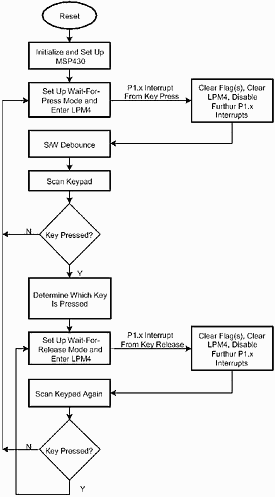
When a key is pressed, the column associated with that key gets a rising edge, waking up the MSP430. At that point, Timer_A is configured to perform a debounce delay of about 40 ms. The timer for the delay uses the internal digitally controlled oscillator (DCO) of the MSP430 - an RC-type oscillator. The DCO is subject to tolerances, so a debounce delay was chosen to give a worst-case-minimum delay of 25 ms. That translates to a worst-case-maximum delay of about 86 ms and a typical delay of about 40 ms. This is a useable range for keypad debounce.
After a key has been pressed, the MSP430 goes into a wait-for-release mode in which it drives high only the necessary row for the key being pressed (other rows are driven low). It reconfigures the P1.x I/O lines to interrupt on a falling edge, and it goes back into low power mode 4, waiting for the release of the key. Again, there is no polling necessary at this point. The detection of the key release is completely interrupt driven allowing the microcontroller to stay asleep while the key is held, thus reducing current consumption. Once the key is released, the debounce delay is again executed. After the debounce delay, the keypad is scanned again to determine if any other keys are being held. If so, the wait-for-release mode continues, waiting for all keys to be released. When all keys are released the MSP430 goes back to the wait-for-press mode again.
During the wait-for-release mode, only one row of the keypad is driven high, therefore limiting the maximum amount of current consumption to the condition where all three keys on a single row are pressed and held. For a 3 V system, that equates to about 2 µA. Any other key press does not result in increased current consumption because the corresponding row is not driven high.
In this 3 x 4 keypad example, the rows are driven rather than the columns, to limit the maximum current consumption by the circuit when all keys are pressed and held simultaneously. Had the columns been driven instead, the rows would have had the pulldown resistors, therefore increasing the number of paths to ground when all the keys are held and increasing the possible current consumption.

The software
The software flow chart is shown in Figure 2. Click here for the complete code listing.
For more information contact Avnet Kopp, 011 809 6100, [email protected], www.avnet.co.za

© Technews Publishing (Pty) Ltd | All Rights Reserved