


Some OEM radio manufacturers tout high receiver sensitivity as the miracle cure for increasing distance and reducing power consumption. They claim a receiver sensitivity of -110 dB delivers up to 10 times the distance of an industry-average radio with a receiver sensitivity of -93 dB - at no cost.
In a make-believe world with only two radios such an argument can be made. However, in the 21st century with countless numbers of radios operating in any given area at every moment, it simply has no merit. This article explores why today's premier radio manufacturers build their products with a receiver sensitivity of -93 dB. It also elucidates the key issues associated with measuring and implementing these systems.
As much as OEMs would like it, there is no magic potion able to increase receiver sensitivity - it is a design consideration. Global positioning systems (GPS) retailing for less than $100 with receiver sensitivities of better than -130 dB have been on the market for years. However, the key to these systems is that they require ultra low data rates and must receive from a limited number of transmitters orbiting the earth. No other interfering devices are in the band. As a result, GPS is the ideal application to deploy great antenna technology and maximum receiver sensitivity.
Going the distance
Few things in life are free, and receiver sensitivity is no exception. Although high receiver sensitivity will not add hardware costs, users pay a heavy price in system performance and maintenance. Consideration, clearly, must also be given to interference and data throughput when designing radios - not just distance alone.
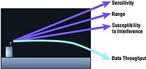
Radio designers today typically employ three methods to improve distance: antenna gain, receiver sensitivity, and transmit power. Each of these has a number of strengths and tradeoffs as discussed below.
Increasing antenna gain - is potentially the most elegant solution. It enables radios to transmit to a desired destination without venturing into unwanted areas or creating unnecessary interference. While this requires a variable and moving antenna and may seem overcomplicated, the result is extreme range, extending the reach of Wi-Fi from tens of metres to kilometres. The tradeoffs are cost and feasibility.
Receiver sensitivity - Using receiver sensitivity to extend distance requires your radios to 'hear everything'- a viable solution for only two devices. With multiple radios, this approach is like trying to listen to just one person in a crowded room with everybody whispering. The receiver must discern between many wanted and unwanted signals. The problem with implementing this type of system is that there is very limited data throughput. As interfering systems are added, the retries eat-up available bandwidth exponentially, bringing the system to its knees. The tradeoffs are data throughput and interference.
Transmit power - Maximising distance using transmit power alone requires continuously raising the power until the receiver can hear the signal. The problem arises when there are more than two radios trying to communicate. The situation is analogous to increasing the noise level in a crowded room so everybody can listen to the person next to them. This solution can be very expensive and requires significant power consumption. ETSI regulations limit output power in these bands to 0,1 W. The tradeoffs are power consumption and cost.
There are also indirect alternatives to extend range, including protocol, modulation efficiency and repeaters. These approaches should be used with 'well-balanced' radio design techniques to ensure optimal system performance in all applications and environments. An ideal radio design offers dynamic output power, receiver sensitivity, and variable antenna solutions - a challenging and costly combination of capabilities that are hard to find in a single package, but that will achieve the ultimate goal.
Interference
The single largest detriment to system performance in any unlicensed ISM band, including 900 MHz and 2,4 GHz, is interference. In fact, the FCC stipulates that every ISM band product is labelled with 'this product must accept interference.' Due to the nature of the bands, they are popular with consumer electronics such as cordless phones, wireless networks, security devices, video transmission, and many other devices. Microwave ovens are by far the largest source of interference in the 2,4 GHz ISM band.
Noise rejection provided by filters can only help decrease noise outside the desired band. When interfering signals or frequency hoppers are moving throughout the band, there are no methods to eliminate 100% of the interference. The transceiver design must take those issues into account and provide adequate bandwidth for retransmissions or alternatives for increasing power above that of the interfering device.
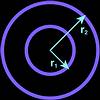
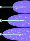
Using the Friis transmission formula shows that doubling distance in line-of-sight conditions requires a doubling (6 dB) of output power or an equivalent increase in receiver sensitivity of 6 dB. This is important when calculating the susceptibility to interference of different manufacturers' products only on the basis of area. Take the case where manufacturer A's product has a receiver sensitivity of -90 dB and manufacturer B's system has a receiver sensitivity of -96 dB. Manufacturer B would be 400% more susceptible to noise than manufacturer A as seen in Figure 1. The susceptibility to interference can be seen in Table 1 for various degrees of receiver sensitivity.
As Table 1 indicates, the manufacturer with the highest receiver sensitivity, manufacturer D, is 64 times more likely than the manufacturer with the lowest receiver sensitivity, manufacturer A, to encounter interference. Moreover, this calculation is a worst case scenario - as the distance will not double with 6 dB improvements in indoor environments. Also, when transmitting great distances, other variables come into play, such as propagation-loss in the plane earth model vs the free-space model, where calculations for distance in free-space or line-of-sight can be cut by 90% for radios less than 1 m above ground.
OEMs planning new products are well advised to measure interference and throughput at varying distances to assess competing transceivers. Recently, Aero-Comm performed such a test comparing a high-sensitivity radio vs the high-performance AeroComm AC4424 under various interference and distance conditions. The results are described in Table 2.
The testing took place in an industrial park after business hours and used a spectrum analyser to ensure an RF-clean environment. Different levels of interference and distances were simulated as follows:
* No interference - nothing operating in the 2,4 GHz band;
* Medium interference - a Panasonic 2,4 GHz handset and base-station were in idle mode; a Linksys 802.11 PCMCIA card and base-station were also in idle mode;
* Heavy interference - a Panasonic 2,4 GHz handset and base-station were off-hook the Linksys 802.11 PCMCIA card and base-station were continuously downloading files;
* Line-of-sight - the interfering devices were placed between the transmitter and receiver of the devices, which were separated by 500 feet;
* No line-of-sight - the interfering devices were placed 50 feet from the transmitting device outside the direct transmission path. The receiving device was placed approximately 1000 feet from the transmitting device, around the corner of a wooden structure.
Variance in measurements is due to positioning, multipath, car traffic, etc. The same software was used to test both the high-sensitivity and the AeroComm transceivers. Under each set of conditions, 100 64-byte packets were transmitted 10 times. The strength of the AeroComm transceiver can be seen under interfering conditions. AeroComm protocol has built-in default RF retries of 16, all of which occur transparently to the OEM. Due to the high RF bandwidth of 576 Kbps, good data packets are successfully received without any apparent impact to the OEM or without affecting overall throughput across the OEM interface. Moreover, the AC4424 hops 75 frequencies instead of 25 frequencies with the high-sensitivity transceiver. When encountering multipath or narrowband interference, the increased number of frequencies provides more immunity to interference.
Measurement techniques
The smaller the signal, the more difficult it is to measure. When comparing receiver sensitivity of -90 dB or -100 dB, one must measure a receiver's ability to detect a signal that is 1 x 10- 9 (one billionth) or 1 x 10⁻¹⁰ (one ten-billionth) of a milliwatt. Extreme care must be taken to eliminate any alternate transmission path when making sensitivity measurements in a lab environment. Alternate paths can include power supply cables, connectors or improperly sealed chambers. AeroComm measurement methodology includes placing the entire receiver in an 'RF-tight' enclosure, including all interface cables and a battery. A highly shielded and grounded cable, which is connected to the antenna port, exits the enclosure through an RF-tight opening. This cable then runs over one hundred feet to a signal source that is also in an RF-tight enclosure. The signal source can be adjusted to determine the minimum signal at which the receiving radio will demodulate data with some acceptable bit-error-rate (BER).
BER is a major factor in determining receiver sensitivity. In order to compare receiver sensitivity between different products or manufacturers, one must ensure that the definition of acceptable BER is the same. This number is rarely if ever specified. AeroComm uses a BER of 1 x 10⁻⁶.
Painted into a corner
OEMs need flexibility for all applications and environments now and in the years to come. If an OEM chooses a one-dimensional transceiver whose major asset is receiver sensitivity, the system may work well for a limited period of time. However, performance is bound to deteriorate when less than perfect conditions inevitably arise and more than two radios are in play. Turning to a higher gain antenna is also not a viable solution, as the antenna is as likely to amplify interfering signals as much as desired signals. Deploying high gain antennas on the transmitters may suffice, and a higher power output could work provided the manufacturer offers these alternatives. However, some are limited by the FCC to 125 mW because they hop only 25 frequencies instead of the industry standard 75 frequencies.
Ultimately, OEMs can best satisfy their needs by choosing a well-engineered solution that can adapt to changes in the industry and their business environment. Moreover, talk to different radio manufacturers' customers and see how their radios are working in the field. Ensure that the manufacturer provides tools at no cost so you can perform your own tests and make your own conclusions. Above all, remember: when it comes to receiver sensitivity, too much of a good thing really is not a good thing at all.
| Tel: | +27 21 555 8400 |
| Email: | [email protected] |
| www: | www.rfdesign.co.za |
| Articles: | More information and articles about RF Design |


© Technews Publishing (Pty) Ltd | All Rights Reserved
 printer friendly version