


High data transfer rates (such as when signals exceed 1 Gbit/s levels), determine the components used in backplanes and connectors. Modern high speed telecom/datacom systems require exacting and precise connector design, especially for differential data transfer in point-to-point applications.
Rather than the previous parallel bus architecture in systems such as VMEbus or Compact PCI, the trend now is towards serial platforms on backplanes with 'switched-fabric-structures'. These fast serial connections satisfy the requirements necessary for increasing bandwidth and the implementation of redundancy for higher security and availability. The PCI Industrial Computers Manufacturing Group's PICMG3-0, and the VME Industrial Trade Organisation's Vita 34, are widely-accepted standards. Both organisations use reliable formats (Europe Cards) and housing systems to IEEE1101.10 and IEEE1101.11 standards. Switched-fabric-architecture not only increases bandwidths but reduces signal paths.
Typical systems have high speed signals in the Gbit/s and also lower, speed ranges. Therefore, both organisations require a combination of IEC-176-4-101, hard metric connectors, and a fast differential connector system that results in the following requirements necessary for next generation telecom computing systems:
* Differential signal transmission.
* Effective screening of the signal pairs within the connector/s.
* High pin density.
* Mechanically strong.
* Simple PCB layout.
* Hot swap possibilities.
* Compatible with existing HM systems.
Standard for high data transfer
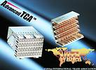
PICMG has specified the ZD connector system from Erni (see Figure 1) as standard for the next generation of Advanced Telecom Computing Architecture (Advanced TCA - PICMG3.0). Its objective is to expand the market for standard products for high speed communication applications up to advanced TCA specifications including PICMG3.1 for Ethernet Fabric, PICMG3.2 for Infiniband and PICMG3.3 for Star Fabric.
The PICM3x specifies a common differential connector family for data transfer. Desired requirements are: support of differential signals; mechanical stability; reliability; ease of manufacture; cost; availability; load capacity. ZD connectors comply with section 2.1.5 PICMG3-0 Base Architectural requirements. Vita 34 standard also specifies ZD connectors for the next Telecom Computing Generation. Vita 34 is based on a switched-fabric concept whereby apparatus can communicate with each other at the same time. The high data rate requires adaption and changes to mechanical cooling plus the connectors. For the subrack Vita has specified a 34 module raster of 1,2 inches (30,5 mm). Modules are 4U and 8U high and 220 mm deep.
Stubbing and skin effect avoidance
Contact raster is a strict criterion in the design of differential signal connectors. Ermet ZD connectors have an optimal contact raster. A wafer raster of 2,5 mm, a 1,5 mm raster between contacts and 4,5 mm between signal pairs (see Figure 2). This reduces noise and allows sufficient room for routing of and the use of wide signal tracks. Relatively wide and longer tracks are possible without two differential pairs having to be routed using vias, thus skin effect frequency-dependent transmission losses may be reduced using wider signal tracks. Track attenuation is determined by the dielectric and losses to ground of the copper lead skin effect.
At high rates frequency-dependent skin effect creates additional losses and reduces signal amplitude. Wider tracks and a thicker copper layer reduce these losses. Simulation and tests have shown that track widths at transfer rates above 2,5 Gbit/s have a significant effect on signal quality. Ermet ZD offers a good and wide routing channel suitable for tracks up to 0,25 mm (10 mil).
Flexible and reliable
Ermet ZD connectors are available in 25 mm modules/configurations: 4 pair version 40 differential pairs; 3 pair version 30 differential pairs; 2 pair version 20 differential pairs.
They are compatible with 10 and 7 row Ermet HM 1EC61076-4-101 connectors. Guides in the housings together with the L-shaped screening contacts ensure positive connections and prevent contact damage. Their optimum design and effective screening prevents crosstalk - crosstalk between signal pairs is limited to 0,75% while the reflection factor is less than 6%.
Measurements support simulation
The performance of Ermet ZD systems as a high speed interface between backplane and cards is verified through measurement. For test purposes, cards are plugged into a backplane and signals applied. The characteristic impedance of differential signal pairs (striplines or microstriplines) is 100 Ω.
Variable measurement parameters include: the distance between cards and backplane (including length of tracks); track width and transmision line (0,15 to 0,25 mm); the backplane material (Fr4, Rogers 4350/4403, Gigaver 210) and the position of the signal layers in relation to the striplines (highest inside, lowest inside).
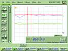
Individual measurements include: crosstalk between two signal points (near and far end); reflection level and the typical impedance of the system plus a diagram showing the various data rates (Figures 3 and 4).
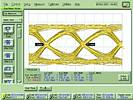
Measurements show basic results including: possibilities of using Ermet ZD connectors for reliable transfer of differential signals at data rates up to 5 Gbit/s and above - also visible on the associated diagram/s. Clearly, systems analysis must take into account all the variables given previously. Also, modern PCB materials with low dielectric losses offer benefits, and reduction of the signal path (about 190 mm) more clearly shows the influences of the other parameters, eg the connectors. It is also evident that the position/s of the signal tracks on the backplane have a large influence on signal integrity (stubbing effect). Press-in version connectors may be used if the tracks are on the top layer (top configuration). Also shorter distances of card to backplane improve results.
Signal integrity sample testing
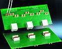
Evaluation kits are available in both single line and multiline versions with which signal integrity and connector systems can be tested. The test kits comprise testboards plus a CD ROM that decribes the test procedure and gives additional technical information.
The single line unit is used for checking: differential impedance of signal pairs; cross-talk between two signal pairs; transfer and reflection levels of signal pairs plus line lag of signal pairs.
The multiline version may be used for testing multiline cross-talk. The kits comprise three different test boards with ErmetZD male connectors - female connectors and special calibration structure (Figure 5), and a CD ROM that describes the measurement set-up, SPICE simulation, component parts and a catalogue.
| Tel: | +27 11 608 3001 |
| Email: | [email protected] |
| www: | www.actum.co.za |
| Articles: | More information and articles about Actum |


© Technews Publishing (Pty) Ltd | All Rights Reserved
 printer friendly version