


This article describes the process of reworking BGA or CSP components when lead-free solder is being used.
Basically, the steps to remove and replace BGA/CSPs are straightforward: 1. Establish thermal profile; 2. Remove failed component; 3. Clean and prepare site; 4. Replace component with flux or solder paste; 5. Reflow; 6. Inspect.
Naturally, convection rather than radiation is the heating method of choice. Using a soldering iron (conduction) is not an option. Using infrared is difficult in normal BGA rework, as the time above reflow can be difficult to control, as ceramic heaters cannot cool down fast. In addition, convection allows for tight process control, which is essential in establishing a good, repeatable thermal profile, one that will not over heat the component, or hold for too long above reflow.
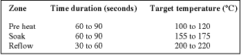
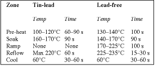
Establishing the correct, ideal profile takes experience and patience, although the basic requirements for any profile are well understood. Standard reflow usually consists of three zones; preheat, soak, and reflow. These are followed by cooling down the PCB to below 100°C. See Table 1.
About lead-free solder
This process is particularly critical when working with lead-free assemblies. The higher temperatures needed for lead-free (up to 235°C) coupled with the thermal sensitivity of BGA/CSPs, can be problematic without the ability to ramp temperatures at a rate that will not harm packages. The latest technology rework systems are more likely to have four heating zones and one cooling zone. Older systems work with a more traditional three-zone model and no system for cooling down. The addition of a controllable pre-heater to a rework system helps meet future process demands, including lead-free. Efficient, controlled pre-heating avoids the thermal damage risked when working with expensive, but sensitive, packages unsuitable for heating above 240°C with quick reflow times.
Temperature specifications
Generally, BGA has a problem with warping causing bridging in the corners, when an air temperature over 300°C is used. This is a condition known as 'dog earing'. Therefore, 265°C to 285°C air temperature is used in the reflow zone as the maximum air temperature. The temperatures used in lead-free are being tightened up by both the suppliers and solder manufacturers, as solder paste needs much higher temperatures. The maximum solder temperature normally used has a peak of 235°C and a low of 217°C.
Component suppliers' maximum temperature, at the component lid, is 265°C, with the most common temperatures ranging from 240 to 250°C. This is very close to the solder temperature, which is 225-233°C. In addition, the time above reflow has gone from 60-90 seconds for eutectic solder, to 15-30 seconds for lead-free. This is three or four times less at the peak temperature time for lead-free than for eutectic.
This means that the rework system has to ramp up very fast and down again to achieve this small peak temperature.
Components with lead-free availability
Many manufacturers are making the transition to lead-free balls optional. However, standard balls still are eutectic in the USA. Japanese component manufacturers have taken the initiative and offer lead-free as a standard. Components without solder balls, such as LLP (generic name LGA) leadless lead frame package, have a very small amount of solder on pads, which are flat. However, these can still be used in lead free. Although the plating is tin-lead, the quantity of lead is very small compared to the overall joint size. For companies that want 100% lead-free these components can be ordered as a special lead-free part.
If lead-free parts are used in regular solder process, then the process will not have to alter. Therefore, the trend for component parts in the future is no lead present. This will help the manufacturers sell to both lead-free companies, and those still doing tin-lead soldering, with only having to make one style of component.
New delta considerations
Other factors requiring consideration are the delta (difference in temperature) across the surface of a part, which high quality rework and assembly companies always consider being a factor. Usually, a delta of 10°C is considered acceptable. New lead- free needs 5°C if possible.
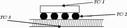
The second new delta is for thermal strength. It is the hardest to achieve, as this is a delta from top to bottom. From tc/1, tc/2, tc/3 all have to be within 10°C of each other. This is from the lid to the ball and under the surface of the bottom of the PCB as shown in Figure 1.
Some designers are not putting components under the BGA due to, if there are any parts under the PCB, they will reflow. Some specifications from manufacturers do not mind if the parts reflow, usually when smaller parts are used. For example, in a cellphone, to achieve the delta across a smaller part is not so difficult especially on a small PCB. The larger the BGA the more difficult this is to achieve.
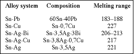
Different lead-free compositions exist and these will be fine tuned as time and processes mature. The most common are listed in Table 2.
Various solder paste compositions
The wetting and temperatures need to be controlled to assure there is no embrittlement at the joint. This means better control of heating, and faster ramps up and down, particularly in the under-board heater. Hot plates are a thing of the past and cannot ramp up or down to work lead-free. For example, in the production reflow oven, the ramp is controlled by the belt speed. The oven has static convection zones and the speed from one zone to next alters the ramp.
In rework, one should never move the PCB while the joint is molten or the PCB is above the glass transition temperatures. Therefore, in rework where the PCB is moved away from the heat source, and the heat continues to radiate up, the time above reflow will be affected in a uncontrolled manner and is not desirable. Times above reflow vary from 15 seconds to 30 seconds where normal solder dwell times are 45 to 60 seconds for no-clean eutectic solders.
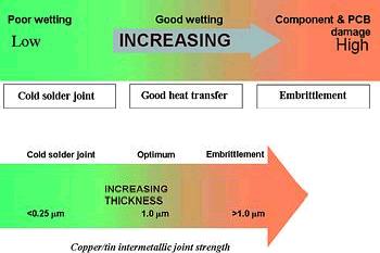
Temperatures must be (see Figure 2):
* High enough to melt solder and form intermetallic.
* High enough to activate flux and cause wetting.
* Low enough to avoid damage to components and PCBs.
Thermal profiles are completely different for lead free, with very close tolerances that are hard to get for the rework process. An example of the standard profiles used for eutectic solders is shown compared to lead-free solder profiles. The key is control and being able to ramp faster and cool quicker from higher temperatures (see Table 3).
Eutectic solder reflow rework
As described earlier, time above reflow is limited to as little as 15 second and some have 30 seconds. However, delta across the surface and top to bottom are very important to get thermal strength into the joint. The bigger the part, the bigger the TCE difference will be.
The distance to neutral point is from the centre of the component to the corner. If the expansion of the part is not matched to the PCB equally, then the joints in the corner are under stress, which is thought to be more critical for lead-free than for eutectic solder joints. Examples of lead-free profiles are shown in Table 3.
Inspection of lead-free is different
Solder joints that are different in appearance and look grainy are usually rejected for quality in normal eutectic soldering. (See Figures 3 and 4). However, this is normal and a completely new standard to be implemented for a company going into lead free.


The traditional method to inspect BGA/CSP joints is with X-ray. This can still be used, however, the quality of the joint appearance will never be seen. A relatively new inspection system, in the last two years, has been vision inspection. This is a complement to X-ray although, due to cost, companies have made this their only inspection system. The cost is typically $20k to $25k, compared to X-ray at $75k to $120k.
Vision inspection will be more important for lead-free as the joint exterior surface will be a good indication of the process control needed to get good solder joints. One other difference between X-ray and a good vision system is the ability to look at the joint, both top and bottom of the ball, to check the formation of the intermetallic joint. This is difficult to see even with the most expensive X-ray system.
Vision systems need to control the light from the front and do not need a lot of light from the back, or the picture will be very bright and look shiny. The ability to look under CSPs and BGAs is also a mandatory requirement for these types of inspections.
For instance, a CSP which is lower mass than a BGA, could get hotter if the process in the oven is not controlled well. It will need to be inspected if it is on the same PCB as a large BGA, which is very common occurrence these days.
CSPs have a stand-off height of 0,2 mm, and BGAs 0,5 mm. Therefore, when choosing a vision inspection system it will need to get down under these parts easily.
| Tel: | +27 11 704 6677 |
| Email: | [email protected] |
| www: | www.testandrework.co.za |
| Articles: | More information and articles about Test & Rework Solutions |






© Technews Publishing (Pty) Ltd | All Rights Reserved
 printer friendly version