


Over the past few years, the relentless trend to ever-smaller components has steadily increased the requirements for rework systems. Additionally, the use of BGA/CSP/micro-SMD architecture makes it more difficult to subject the placement procedure to a visual control.
Proven techniques are at hand for the soldering and desoldering of assemblies which can be easily integrated into the smallest rework facility. The placement accuracy of most systems, meanwhile, is always a function of their mechanical precision. Required are a high degree of rigidity for the mechanical construction and a certain size and weight of the system. Smaller components and finer pitches obviously require a higher degree of accuracy. It sometimes may even be necessary to alter the constructional principles to achieve that.
Another problem of rework systems concerns their handling. Most placement manoeuvres must be carried out manually by the user. Camera systems or microscopes are available for control purposes. For the user this means that he must maintain peak levels of concentration for long periods at a time. Whether he manages this or not is the first if not the only condition for a successful placement and rework.
The engineers at Martin have now developed an innovative rework system called the auto vision placer (AVP). The mechanism to provide mechanical precision has been much simplified, and the result is an easy-to-apply and elegant user interface for the semi-automatic placement of components. The rework quality will depend much less on the concentration level and the general ability of the operator.
Simplifying the system to provide mechanical precision while maintaining the highest possible degree of placement accuracy: this circle can only be squared by using a sensor to control and, if necessary, to correct the position of the component. Since cameras are already in place to perform their visual control tasks, the use of an image processing technique has an obvious advantage. Using the camera as a sensor produces another substantial benefit: the absolute accuracy of the sensor increases proportionally to the size of the component.
Practically, objectives with a 10-times magnification are used for BGAs (42 X 42 mm), objectives with a 20-times magnification are used for CSPs (16 X 16 mm) and objectives with a 40-times magnification are used for micro-SMDs (8 X 8 mm).
The overall system, Figure 1, has been designed to deliver a robust and precise automatic placement and to require the operator to carry out no more than a few simple tasks.
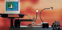
A brief outline of the system
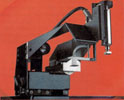
The system features a light arm that can be manually positioned on a massive base plate and fixed with the help of a magnet switch. A mirror and camera with a removable objective have been integrated into the arm, allowing the operator to watch the circuit board vertically from above without needing a tall tower structure. The system is also equipped with a 4-way-movable (2-times translation, rotation and z-lift), automatically-powered draught pipette with quickly interchangeable insertion pipette and a two-way fastener for the solder stick.
The working principle of the placement technique is relatively simple. Once the target area of the component (following the 'rough positioning' by hand) has entered the field of vision, ie, once it has been identified to the system, this position can be saved (ie, both camera and circuit board are fixed). If now the component - which has been inserted into the suction pipette - is equally moved into the picture, also making it possible to identify its precise position, the system can simply calculate from the actual and the target position data where the component needs to move.
In comparison with split-optical techniques, the method of 'virtual superimposition' produces superior results because it enables the component to be moved barely above circuit board level. This reduces the movements along the z-axis and substantially simplifies the machine mechanics. For all split-optical systems, the two optical directions need to be calibrated with the highest possible degree of accuracy. The required movements of the optical system cannot afford the slightest slackness. Mistakes (eg, a flawed calibration) do not become immediately obvious to the operator. This creates substantial risks. The camera of the auto vision placer, on the other hand, can directly observe the mechanical movements without the optical paths being divided in any way.
The problems of image processing
There are currently no techniques for the automatic and robust reading of components' target areas and for the establishment of the components' position under a wide range of lighting conditions and an equally wide range of boards and components. The application of simplified techniques which would work only in certain environments is not feasible for the purposes of a rework technique. This is why the auto vision placer has been based on the idea of using the operator's intelligence to keep the image processing easy and robust.
For instance, in stage one the operator is prompted to identify the component's target zone by marking three points. The results are displayed to allow the operator to check immediately whether everything is fine. The component is then moved to enter the picture after which the operator again marks the actual position with his mouse. Both actual and target positions are therefore clearly identified, making easy what would have been the image processor's most difficult task.
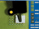
The fine positioning which is so difficult for the operator is, on the other hand, a relatively easy task for the software and the machine. The pipette has been marked with a little white indicator that can be easily followed by the moving camera. This helps immediately correct positional inaccuracies of the translatory axes. In order to control the rotary axis, the software can calculate the rotary angle by observing the mark and precisely recording its translation.
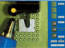
Once the right place for the component has been automatically found, both co-ordinate systems are moved into absolute congruence (pixel by pixel), and the component can be placed, Figure 5. Potential parallactic errors in the final stage of placement can be identified and, if necessary, corrected.
The software has been designed to allow the automatic adaptation of all parameters to any particular machine (eg, the permissible variations of the manufacturing process) within five minutes by special calibration software.
The smaller the component, the greater the accuracy
This giant leap in rework technology is made possible by a robotic control system that does not predominantly rely on the route sensors but which is instead, provided (by the camera) with exact information about the actual location of the insertion pipette at any time in the process.
The rework, dispensing and soldering specialists at Martin have developed an innovative concept that not only allows the operator to work comfortably but also with a target accuracy out of the reach of (commercially viable) mechanical systems. This system was conceived as a radical alternative to the conventional automatic assembly units which move blindly into the target area and need exact path measuring systems and heavy equipment support. It could be said that the system imitates the cleverness of Mother Nature - if one imagines the way a hawk spots a mouse on the ground and then captures it in full nose-dive flight. The hawk cannot calculate its entire trajectory before it begins descent: it only catches the mouse by correcting its direction while already nose-diving - something it can do easily because the object becomes bigger in the field of vision the closer it comes.
This 'hawk's eye function' in the auto vision placer is fulfilled by the camera. The motto for this is: 'the smaller, the greater'. The auto vision placer is capable of placing a BGA with an accuracy of ±0,13 mm, for a CSP the tolerance range shrinks to ±0,05 mm, and the tiny new micro-SMDs can be located with an accuracy of ±0,03 mm. In a direct comparison with conventional split-field systems, the auto vision placer provides the superior solution in a number of ways:
* The operator can control the process with his mouse on the screen; this is less stressful for him and faster.
* The AVP-arm solders and desolders automatically.
* The placement accuracy is subject to the resolution of the camera image, since the movements of the x-y- and the rotary axis are controlled by the video image and not through mechanical measuring systems. The optical path of the image is not changed by movable parts such as mirrors at any stage of the process.
| Tel: | +27 11 609 1244 |
| Email: | [email protected] |
| www: | www.zetech.co.za |
| Articles: | More information and articles about ZETECH ONE |


© Technews Publishing (Pty) Ltd | All Rights Reserved
 printer friendly version