


Saving power, many portable devices use white LEDs as a means of display illumination. This article explains how a high-efficiency driver IC simplifies design of the LED driver circuitry.
The explosive growth for colour displays in portable appliances has been fuelled by the consumer's need to display more information and the introduction of built-in (or 'snap-on') cameras. In parallel with this growth, the development of high-efficiency white LEDs has made them an attractive alternative to illuminate the display. For all colours to be displayed correctly, under all ambient light conditions, a broad-spectrum light source is needed (ie, white light). Many different backlighting technologies are available for this, eg, cold cathode fluorescent lamps (CCFL), electro-luminescent lamps (EL) and more recently, white LEDs. However, while the first two alternatives require a high AC voltage of several hundred volts, the white LED can be driven from a low-voltage source under 5 V. It is this characteristic that makes white LEDs very attractive, particularly for battery-driven appliances.
Challenges
For a white LED, the brightness is, (logarithmically) proportional to the forward current through the diode. For current to flow, the diode must be biased with a voltage that is in excess of its forward voltage drop. The diode forward voltage drop is a characteristic of the LED colour and hence the material used to manufacture the diode. Some examples are: blue 4,5 V, white 3,6 V, red 2,0 V.
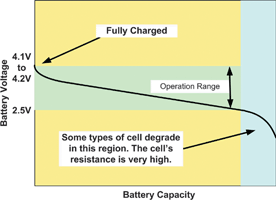
The dominating power source for handheld products is a Li-Ion or Li-Polymer battery. This battery type has a cell voltage that ranges from 4,2 V (depending on type) down to about 2,7 V during the discharge cycle. Therefore, to be able to drive the white LED during the whole discharge cycle, the battery voltage must be boosted from 2,7 V at its lowest, to a minimum voltage of 3,6 V. Either a DC/DC boost converter with an external inductor can be used to achieve this or alternatively the voltage can be boosted and regulated with a capacitive DC/DC converter or so-called 'charge pump'.
In many applications, it is important to be able to control backlight brightness. This can be accomplished in two ways, either via constant regulation of the current through the diode, or via PWM control to set and control the current. Usually a PWM frequency between 100 Hz and 10 kHz is used to control the current for maximum brightness between 15 and 30 mA.
In a typical application, several LEDs can be used to provide a complete solution. In this case, one problem to consider is that due to manufacturing process variations, the forward voltage drop of a particular LED can vary from diode to diode. This variation can lead to deviations in brightness levels between the LEDs, depending upon how they are connected. Connecting all the LEDs in series ensures that the same current will flow through all of the LEDs, therefore they all emit the same brightness. However, the disadvantage of this is that it requires a higher compliance voltage for forward conduction (eg, six diodes in series would require a minimum of 22 V (6 x 3,6 V) for correct operation). In addition, a white LED can fail open circuit, cutting off the supply to the other diodes. Therefore, not only will the backlight be completely off, additional damage may occur due to the inductive DC/DC converter increasing the output voltage to values in excess of component operating limits, while trying to maintain a constant current in an open loop.
Variations of this arrangement use parallel branches of serially-connected diodes, eg, two branches with three LEDs in each branch. There will be a difference in forward voltage drop between each of the diodes, but as there are several diodes in each branch, then generally the difference between the branches will be averaged out to become more or less equal.
Using a resistor in every branch can decrease the influence of a varying forward voltage drop. If the LEDs' forward voltage drop is less than the nominal value, the current will increase. This leads to an increased voltage drop over the resistor and then again a decreased current. The resistor therefore provides negative feedback. On the other hand, there is now yet another component dissipating power and therefore reducing efficiency.
Methods for power conversion
One of the most important parameters to consider in selecting a backlighting solution is the efficiency. Maximising battery life is a key design parameter and, if the efficiency of the chosen solution is low, then equipment operation time and standby time are severely reduced. There are several different methods for voltage conversion and white LED driving. As mentioned earlier, both inductive and capacitive DC/DC converters are used. They can be either constant current or constant voltage topologies. However, it is not so easy to compare the efficiency between different topologies. Since the brightness is proportional to the current, the best way to compare the efficiency is for a given diode current, to look at the total input power to the DC/DC converter.
Capacitive converters with constant output voltage
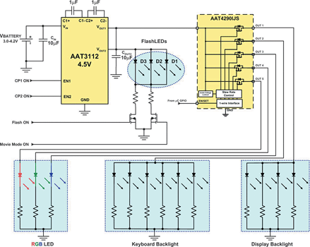
Many of the commercially-available LCD modules already include the LEDs and bias resistors for the backlight. The LEDs are often connected in parallel. Those modules only require a single 5 V supply. In this case, a constant output voltage, capacitive DC/DC converter, could provide a solution. AnalogicTech's AAT3112 is an example of such a device; requiring only four small, external components, the AAT3112 can source up to 500 mA of pulsed current, and is available in a 16-pin 3 x 3 mm QFN package. The maximum efficiency is as high as 83%.
Capacitive converters with constant output current
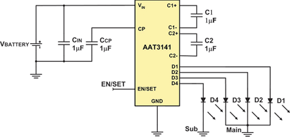
A third type of converter is represented by AnalogicTech's AAT3141 capacitive DC/DC converter with four constant current outputs. This low noise driver IC uses constant frequency tri-mode, (1x), fractional (1,5x) and doubling (2x) charge pump conversion to maximise efficiency while controlling white LED brightness, without the need for ballast resistors but with accurate current matching.
Having three operation modes ensures that a very high efficiency is achieved over the whole Lithium-Ion battery voltage range. If a pure voltage doubler were used, the output from a fully charged battery would be in excess of 8 V. Regulation down to 3,6 V would then be required, representing a significant power loss. If the battery voltage is increased only 1,5 times, this loss is decreased and the efficiency will be much higher. When the input voltage is higher than the forward voltage for the LED, the AAT3141 enters 1x mode controlling the current in a linear fashion without using the charge pump at all. The switchover between the 1x, 1x and 2x mode is fully automatic and transparent to the user. One should also note the typical white LED VF is around 3,5 V. The Li-Ion battery in most applications spends most of its useable life (87%) at and above 3,6 V. Thus, for close to 87% of the discharge cycle, the 3141 operates in 1x mode consuming only 500 μA with an excellent efficiency.
Having a 2x doubling mode ensures that even during a GSM transmission burst (when the battery voltage might decrease up to 400 mV) there will be enough voltage to keep the programmed current and avoid flickering of the backlight.
With four 30 mA outputs, the AAT3141 uses a single wire to control the brightness level in 32 independent steps. Outputs can be paralleled for driving higher current LEDs or the outputs can be used individually. The output drivers are very flexible and can be operated either as a group of four, with all outputs programmed to the same brightness level, or as a group of three and one, where the output brightness can be controlled independently. The latter is for applications where there is a main and a sub-display. Again, this is achieved with a single control wire.
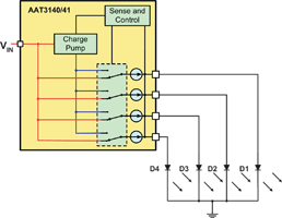
Utilising a proprietary switching arrangement between the internal power supplies and each output, the AAT3141 monitors each diode and selects the optimum power supply voltage according to the VF of the diode being driven. This ensures that no unnecessary power is wasted. In less efficient, competitive solutions, only one diode is monitored which could result in the remaining LED driver stages dissipating excessive power. Compared to competitive solutions, the AAT3141 uses up to 25% less current.
AnalogicTech's Simple Serial Control (S2Cwire) digital input is used to enable, disable and set the LED drive current with a 32-level logarithmic scale LED brightness control. In the majority of competing converters, the diode brightness is controlled by a low frequency PWM signal between 100 Hz and 10 kHz. As this is within the audio frequency band, additional filtering may be required. Alternatively, the current could be programmed with an external resistor. The simple single-wire interface used in the AAT3141 results in lower noise and better accuracy over temperature than competing resistive solutions.
Brightness (light) is logarithmically proportional to the LED current, and the output current from the AAT3141 is programmed accordingly. Therefore, every step change in current will result in an even change in brightness. 32 steps are sufficient to simulate a step-less increase/decrease of brightness if required.
The AAT3141 is available in the very small 12-pin (2,85 x 3,00 mm) TSOPJW package. Also available is the AAT3140 for applications with one display.
Conclusion
The choice of converter depends on many design criteria. It is important not only to look at the efficiency but also to carefully study how the LEDs are connected in order to minimise brightness differentials. Noise, number of external components, control and, not least, price are other important parameters to consider when selecting a backlighting solution.
For more information contact Hi-Q Electronics, +27 (0)21 595 1307, [email protected]
| Tel: | +27 21 595 1307 |
| Email: | [email protected] |
| www: | www.hi-q.co.za |
| Articles: | More information and articles about Hi-Q Electronics |


© Technews Publishing (Pty) Ltd | All Rights Reserved
 printer friendly version