


Articles about the universal serial bus (USB) used to begin by justifying USB as the new connection standard for personal computers. Thankfully, this is no longer necessary. If you have an embedded system and want to connect to a PC, the mainstream conduit is USB.
After introducing a new chip that makes it easy to add USB to any system, this article focuses on the SPI interface, providing example C code for a generic SPI implementation. The article concludes with code for a simple USB HID (human interface device) - a 'Windows Panic Button.'
Adding USB to anything
Microprocessor choices are often made based on integrated peripherals. Some processors include USB functionality, but most, especially the really low cost ones, do not. Have you ever chosen a microprocessor with the perfect combination of I/O and peripherals, but found that it lacks USB? Would it not be nice to design a USB peripheral without having to buy new tools and learn another processor?
It is now possible to add USB to any microprocessor with a new Maxim Integrated Products chip, the MAX3420E. This chip provides a USB full speed transceiver, an intelligent USB serial interface engine (SIE), and an SPI slave interface that can run with an SCK clock signal up to 26 MHz. The MAX3420E operates as a full-speed USB peripheral with one control endpoint, two double-buffered 64-byte data endpoints, and one 64-byte interrupt endpoint.
Bus-powered widget
Figure 1 illustrates a common USB peripheral architecture. The USB Vbus wire provides 5 V power to a 3,3 V regulator, which powers the micro and the MAX3420E (no wall wart needed!). The SPI interface can comprise three, four or five wires. The basic SPI signals are SCK (serial clock), CS (chip select, which frames an SPI transfer), MOSI (master out, slave in data) and MISO (master in, slave out data). Some interfaces can combine MOSI and MISO as a bi-directional pin, giving a three pin interface.
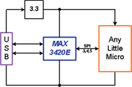
The MAX3420E also provides an interrupt pin to reduce traffic over the SPI interface. Instead of exercising the SPI port to poll bits for USB activity, a μP can simply poll the INT pin for activity, or for more complex systems, use it as an actual interrupt.
What if the μP does not have an SPI port? No problem - it is very easy to make a firmware-driven SPI master by directly toggling general-purpose I/O pins. A strong feature of USB is that it is self-throttling; it automatically accommodates any speed interface on the SPI side. (It does this by using a NAK handshake on the USB side to indicate 'busy now, try again'.) Many USB peripherals, especially those connected to humans, can operate very responsively with even the slowest SPI interface.
What if the μP in Figure 1 is really small, say, under 10 pins? Do you not use μP precious I/O pins just to talk to the USB chip? Yes, and this is why the MAX3420E provides four general purpose inputs and four general purpose outputs to replace the pins used to talk to it, and then some. So your system actually gains I/O pins after connecting a MAX3420E.
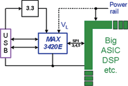
The MAX3420E is not restricted to small systems. Figure 2 illustrates how to add USB functionality to an ASIC, FPGA, DSP, or other large chip. An obvious reason to do this is that the big chip may not have USB built in, or the USB inside may not be exactly what you want. Another good reason for this architecture is that as large chips shrink in process geometries, they are less able to touch 'high' voltages like the 3,3 V required by USB. The external USB chip with a low voltage SPI interface is a good answer. To run the low voltage interface, the MAX3420E has internal level shifters and a VL pin to set the operating voltage of the interface pins to anything between 1,7 V and 3,6 V.
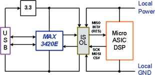
As shown in Figure 3, the SPI interface is also an easy place to put an optical isolator, since the signals are unidirectional, and they can be programmed to run relatively slowly to support low cost optos.
The SPI interface
SPI (serial peripheral interface) is a simple serial interface that uses two data lines, a serial clock, and a chip select signal. The SPI master drops CS# low to start a transfer, and then drives the serial clock SCK to simultaneously clock data in and out of a slave device. The SPI master terminates a transfer by returning CS# high.
The SPI interface has four clocking modes, reflecting two mode signals called CPOL (clock polarity) and CPHA (clock phase). These signals are represented in the form (CPOL, CPHA). It turns out that an interface that expects positive edge SCKS and which also expects the MOSI data to be available before the first positive clock edge can operate in modes (0,0) and (1,1) without alteration. This property allows the MAX3420E to operate in mode (0,0) or (1,1) without requiring a mode pin.
Figure 4 illustrates a data transfer between a microprocessor (the MAXQ2000, described later) and the MAX3420E using SPI modes (0,0) and (1,1). The difference is the inactive level of the SCK signal, low for mode (0,0) and high for mode (1,1).

The MAX3420E accepts a command byte as the first byte of every transfer. The command byte contains the register number and a direction bit. The second and subsequent bytes contain data. You may be wondering what is coming out of the MAX3420E (MISO) while the command byte is being clock in (MOSI) in Figure 4. These are eight USB status bits that are available every time a command byte is clocked in. This feature is active only for interfaces that use separate data pins MISO and MOSI.
SPI code
The trick to writing general C code for the MAX3420E is to isolate the bare minimum SPI operations in a separate module, and customise only this module from SPI interface to SPI interface. At a minimum, this module needs to do only three things: initialise the SPI port, read a byte and write a byte.
The example application in this article uses a hardware SPI unit. For SPI masters that do not have one, we will first look at some generic C code for a bit-banged SPI interface.
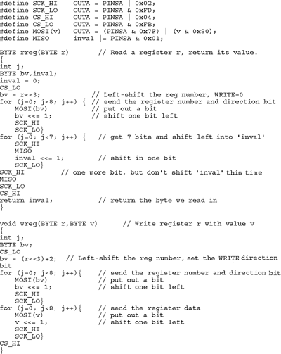
Bit-banged SPI: The function that initialises the SPI port will change the most from processor to processor. It is responsible for assigning the particular I/O pins used by the interface, setting their directions, and then setting the initial conditions of CS=1 and SCK=0 (we are assuming a mode (0,0) SPI master). Listing 1 shows generic routines to read and write MAX3420E registers. The macros at the beginning define the low-level pin operations to drive SCK high and low, drive CS high and low, and clock data in and out using the MOSI and MISO pins. The macros insulate the functions from various I/O schemes of various microprocessors. Use of macros makes the code easy to read and processor independent. The macros in <a href= http://www.dataweek.co.za/articles/Dataweek%20-%20Published%20by%20Technews/w9292.doc " target="_blank">Listing 1</a> are for a typical older microprocessor that does not contain a hardware SPI unit.
For a clearer version click on <a href= http://www.dataweek.co.za/articles/Dataweek%20-%20Published%20by%20Technews/w9292.doc " target="_blank">Listing 1</a>
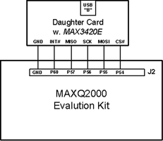
Hardware SPI: Tom Cantrell introduced the MAXQ2000 to Circuit Cellar readers in the September 2004 issue. In brief, the MAXQ2000 is the first of a family of low power, high performance RISC processors from Dallas/Maxim. The 'Q' stands for Quiet, indicating that the architecture is designed to coexist nicely with sensitive analog circuits. From a USB interface standpoint, the MAXQ2000 is especially friendly to the MAX3420E because it has a built-in SPI port (see Figure 5).
Part-II
In the second part of this article, we will have a look at an example that uses the MAXQ2000 development kit and the MAX3420E to build a simple but interesting Windows widget. Part II of 'Add USB to anything" will follow in a subsequent issue of Dataweek.
| Tel: | +27 11 608 0070 |
| Email: | [email protected] |
| www: | www.cstelectronics.co.za |
| Articles: | More information and articles about CST Electronics |


© Technews Publishing (Pty) Ltd | All Rights Reserved
 printer friendly version