


After introducing the new Maxim chip that makes it easy to add universal serial bus (USB) connectivity to any system in the first part of this article, we shall now have a look at its application for a simple, but interesting, USB human interface device (HID) - a 'Windows panic button'.
We shall look at an example that uses the MAXQ2000 development kit and the MAX3420E USB device. From a USB interface standpoint, the MAXQ2000 is especially friendly to the MAX3420E because it has a built-in SPI port. Figure 1 shows the port-to-SPI signal assignments to serve as a reference for reading the program listing.
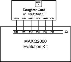
The MAXQ2000 hardware SPI unit provides SCK, MOSI, and MISO, but not CS#. Because of variations in how CS# operates (for example for accessing one byte versus a burst of bytes), it is better to use a general-purpose I/O pin for CS#.
Figure 2 illustrates the basic MAXQ I/O cell. Every I/O cell has a flip-flop, which in this example is written using a bit called PO5.3. The 'O' stands for output. You can always write to this flip-flop; whether or not it gets connected to the pin depends on the direction bit. When configuring an output pin, it is good practice to write to the flip-flop before connecting it to the pin, to avoid glitches.
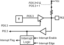
The direction of the P53 pin is set by a bit called PD5.3. D stands for direction, and the D signal serves as the output enable for the pin driver: 1=drive, 0=float.
The state of the pin can always be read in a bit called PI5.3. I stands for input. No matter how the pin is driven, by the internal flip-flop (PD5.3=1) or by something external (PD5.3=0), the PI bit indicates the pin state.
A nice feature of this structure is that if the pin is configured as an input (PD5.3=0), the output of the flip-flop is not used as an output, and therefore it can be re-used as a pull-up resistor switch. When D=0, the O signal is redefined to mean 'connect a pull-up resistor', as shown by the dotted line and switch in Figure 2.
Some I/O pins have interrupt capability, shown by the lower block in Figure 2. Interrupt blocks have three signals. A flag bit is set when the interrupt request is active, and is reset by the CPU.
An edge-select bit determines whether a positive or negative signal transition causes the interrupt request. And finally, there is an interrupt enable bit for each pin capable of requesting an interrupt.
Our example app configures the MAX3420E INT output pin for a positive edge-triggered interrupt. On the MAXQ2000 side, the code directly tests the interrupt flip-flop for a pending USB interrupt, rather than using the MAXQ2000 interrupt system. The program does nothing but check the status of a pushbutton and respond to the USB requests, so a polling loop is all that is needed.
MAXQ2000 I/O pins are shared between general purpose I/O and special function hardware such as the SPI unit. To use special hardware, you first configure the hardware block, and then enable it to connect it to the I/O pins. The SPI_Init() routine in the full listing sets pin directions, configures the SPI interface, and finally enables it.
The functions 'rreg' and 'wreg' in the full listing take advantage of the MAXQ2000 hardware SPI unit, and therefore are smaller and faster than their bit-banged counterparts.
Source code: The full source code listing can be found posted with this article by clicking on 'source code' above, alternatively, e-mail [email protected] with 'Code' as Subject, to get it sent to you.
Example: a 'Windows panic button'
This USB widget is a USB HID featuring a single button. When you press the button, all active windows are minimised and you are looking at your desktop. Push it again, and all the application windows spring back to life.
USB keyboards are interesting - if you plug in several, they are all active at the same time. So our little panic button works in conjunction with your normal keyboard.
If the PC suspends, the panic button takes on a new role - it can serve as a remote wake-up button for the PC. This is highly dependent on whether or not your PC supports wake-up from USB. Some do, some do not. This button can help determine if yours does.
The code example runs on the MAXQ2000 development kit with a small USB daughter board (containing the MAX3420E) plugged into an expansion connector. The code is actually a reduced version of more extensive USB code examples that are available on the Maxim/Dallas website.
USB details
This app contains USB boilerplate code that does the nitty gritty work of enumeration. The personality for this device is completely described by the character arrays in the Panic_Button_Enum_Data.h listing in the code.
This app uses two endpoints, the mandatory CONTROL endpoint zero, and EP3-IN, a single-buffered 64 byte endpoint. Although the MAX3420E contains two double-buffered 64-byte endpoints (EP1-OUT and EP2-IN), the throughput advantages of double buffering are not needed in this application.
A common HID misconception is that HID devices operate only at low speed. This app demonstrates that even something as slow as a keyboard can benefit from running at full speed, since it uses less bus bandwidth, sending 12 MHz instead of 1,5 MHz packets.
Interrupt endpoints have a polling interval, which determines how often the USB host asks the IN endpoint for data. Every interval we can expect the host to send an IN request to our device's endpoint 3. Figure 3 illustrates a simple state machine that handles these requests. Once the device is enumerated, the µP repeatedly executes this routine. To simplify things, this app polls the interrupt pin for activity, but of course if you have other things going on in the µP you will want to make the Do_IN3 function interrupt activated.
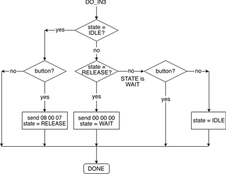
The state machine uses two global variables, state and button. C macros define three states, IDLE, RELEASE, and WAIT. The state variable is initialised to IDLE. The variable button is high if the pushbutton connected to the MAX3420E GPIN0 pin is pressed, and low otherwise. An endless loop in main() increments a button-check timer, and when expired it reads the GPIO register in the MAX3420E to determine button state. This saves unnecessary SPI traffic.
While the button is up, the state diagram takes the two leftward branches and does nothing. If the button is pressed while in the IDLE state, it is time to send the keycode to clear the decks of active windows. This is the sequence 08 (Windows key) 00 (reserved) and 07 (letter d). The next state is set to RELEASE, and we are done.
As soon as the MAX3420E dispatches this packet over USB, it generates another EP3-IN interrupt request to indicate that the EP3-IN FIFO is once again available for loading data. The Figure 3 function is entered again, and this time state=RELEASE, so the function sends the sequence 00 00 00, indicating 'keys up'. The next state is set to WAIT, meaning 'wait for the button to be released'.
Now all the function needs to do is to use the WAIT state branches to detect the button release. While the button stays down, nothing happens. When the button is released, the state diagram takes the two rightward branches and re-initialises the state variable to IDLE, readying the function for the next button press.
The code that executes most of the time occupies only 23 lines of C code. Check out the 'Do_IN3' function to see how the Figure 3 flowchart is implemented.
Code tidbits
A few details lurking in the code deserve comment:
Time-critical USB events: The MAX3420E signals a remote wakeup by driving a 'K' state onto the bus for 10 ms. To relieve the SPI master from the chore of counting off this time, the MAX3420E internally times this signal (and, in fact, all USB time-sensitive events) and then gives the SPI master an interrupt when the interval is complete. The SPI master does not need to tie up its own timers for these events - it just starts the operation and then waits for the completion interrupt.
The ACKSTAT bit: The functions rregAS and wregAS do one thing differently than rreg and wreg, they set an ACK STATUS bit in the SPI command byte. The SPI master (the MAXQ2000 in our example) uses this bit to tell the MAX3420E that it has finished servicing the current CONTROL request, and therefore to terminate the CONTROL transfer by ACKing its status stage. ACKSTAT also exists as an internal register bit, but by including it in the SPI command byte, this frequently used operation can execute quicker and with less code.
readbytes(), writebytes() functions: These functions take advantage of the MAX3420E bursting capability. Instead of sending two SPI bytes per byte access (a command byte and a data byte), they first drop CS#, send the command byte, clock in/out a burst of bytes, and finally raise CS# to terminate the SPI transfer.
Where to find the product ID: The product ID string (in Panic_Button_Enum_Data.h) appears as a little message the first time you plug in your panic button. This pops up during the enumeration process that identifies the panic button as an HID, and associates it with the built-in Windows driver.
Every subsequent attachment is silent except for the little 'ba-deep' Windows sound you hear when you plug in any USB device. If you want to check the device status anytime, go to the 'USB Human Interface Device Properties' screen. You can reach this screen by right-clicking 'My Computer', selecting 'Properties', 'Hardware' tab, 'Device Manager' button, expand the 'Human Interface Devices' item, right-click on 'USB Human Interface Device', and select 'Properties'. You should see a location, and the text, 'MAX3420E USB Panic Button'.
USB compliance
You might look at the code and think this is a lot of work for a one-button USB device. That is because there is a certain overhead associated with any USB device. Fortunately, USB is so carefully specified that the enumeration code can serve as a template (as in copy-paste) for any USB device.
Like all diligent developers, we want our designs to be certifiable by the USB-IF, which (a) gives us the right to use the USB logo, and (b) helps ensure that our design will function without problems on any PC. This app passed the USB Command Verifier (USBCV version 1.2.1.0) and HID tests in the test suite available to developers on the USB-IF website.
In conclusion
If you need to make a USB peripheral, check out the MAX3420E. It is small, easy to program, and comes with lots of free example code. It adds I/O pins to your design, and plays nicely in any system that has SPI support. Because SPI is so easy to bit-bang, this includes every microprocessor. If you want performance, you can clock the SPI interface as high as 26 MHz.
About the author: Lane Hauck works as a senior scientist for Maxim Integrated Products. He has designed FFT analysers, video games, electronic toys, and USB integrated circuits. Lane has a BS in Physics, which he never uses, and an MSEE, which he does. He enjoys music and digital photography.
| Tel: | +27 11 608 0070 |
| Email: | [email protected] |
| www: | www.cstelectronics.co.za |
| Articles: | More information and articles about CST Electronics |
| Tel: | +27 11 458 9000 |
| Email: | [email protected] |
| www: | www.electrocomp.co.za |
| Articles: | More information and articles about Electrocomp |


© Technews Publishing (Pty) Ltd | All Rights Reserved
 printer friendly version