


In Mitsubishi Electric's newly-developed dual in-line package intelligent power module (DIP-IPM) Ver. 3 Series, the company's fifth-generation planar structure IGBTs or carrier stored trench-gate bipolar transistors (CSTBT) have been used to bring to market six new products with rated voltage of 600 V and rated currents ranging from 5 A to 50 A.
Direct driving by the 3 V system MCU is now within range, making it possible to simplify the input interface.
DIP-IPMs are 'intelligent power modules' with a transfer mould structure, developed by Mitsubishi Electric for the home-appliance inverter market, and are used extensively in consumer white goods such as airconditioners, washing machines, and refrigerators. Although there has long been strong demand for smaller, more efficient, power modules with lower noise emission for these markets, recently, the stronger demand is for cost reduction due to the current decline in home electrical appliance prices.
Overview of the series
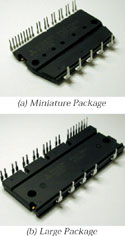
Like the earlier DIP-IPM Ver. 2 series, the new Ver. 3 Series products are deployed in two types of packages, large and miniature, depending on the current ratings. Figure 1 shows DIPIPM Ver. 3 products, and Figure 2 shows the structure within the package. The Ver. 3 miniature package is manufactured from moulded resin after mounting the power chip and the control IC on a frame, and has the exact same structure as the Ver. 2 miniature package. The large package is manufactured by performing resin moulding after first mounting the power chip and the control IC on the frame (the first moulding), and then performing resin moulding again with an aluminum heat sink in place (the second moulding).
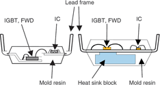
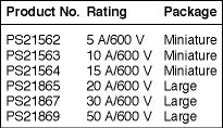
The DIP-IPM Ver. 3 large package is structured using only a single-step resin moulding process after mounting the power chip and the control IC on the frame and after soldering separated copper heatsinks to the back of the frame of the power section. The use of this new package structure in the Ver. 3 large package makes it possible to reduce costs and to increase the capacity by increasing the efficiency of thermal dissipation. Table 1 shows a list of the DIP-IPM Ver. 3 Series product lineup.
As with the DIP-IPM Ver. 2, the internal circuitry in the Ver. 3 comprises a power circuit section (IGBTs and FWDs) with a three-phase inverter structure, and an LVIC and HVICs for control. The LVIC provides IGBT gate-drive function, short-circuit protection, and control supply under-voltage protection, while the HVIC offers IGBT driver function and control supply under-voltage protection.
Power-device technology
The DIP-IPM Ver. 3 Series uses fifth-generation planar IGBTs (0,6 μm design rule) in all products with rated currents of up to 30 A, and uses carrier stored trench-gate bipolar transistors (CSTBTs) in the product with the 50 A rated current. This makes it possible to reduce the saturation voltage and shrink the chip size relative to the DIP-IPM Ver. 2, which is equipped with a fourth-generation planar IGBT.
The CSTBT, which has carrier-storage layer and a carrier concentration distribution nearly the same as that of a diode when in the ON state, is beginning to become practical as the next-generation power device, due to the advantage of enabling a saturation voltage even lower than that of conventional trench IGBTs.
ASIC technologies
HVICs, where 24 V CMOS elements and 600 V withstand voltage DMOS elements are integrated on the same chip, are used as the highside IGBT driver elements in the DIP-IPMs, making it possible for an MCU, etc, to drive the DIP-IPM directly, without the use of an optocoupler. The use of a new process in the control IC has made it possible simultaneously to reduce the chip size and the circuit current. This, in turn, makes it possible to reduce the circuit current for the high-side IGBT gate drive so that the bootstrap capacitance can be reduced.
Packaging technologies
A single-step moulded structure with built-in separated copper heat sinks is used to increase the current capacity of the large-package DIP-IPM. The use of this new structure greatly increases the thermal dissipation capabilities over those of the conventional DIP-IPM Ver. 2 large packages.
Advantages
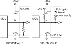
One advantage of the DIP-IPM Ver. 3 Series is its simpler input interface. Typically, MCUs are used to control DIP-IPMs, but in recent years the trend in MCU drive-supply voltages is shifting from 5 V to 3 V. The optimisation of the input threshold values in the DIP-IPM Ver. 3 Series for compatibility with 3 V system input signals enables direct drive by 3 V MCUs and digital signal processors. Furthermore, by using high-active I/O logic (where the output is high when the input is high) and integrating an internal pull-down resistor at the input of the DIPIPM, the need to connect external resistors is eliminated, enabling simplified input-interface circuitry. Figure 3 shows an example of a DIP-IPM Ver. 3 input interface circuit schematic in comparison with that of the DIP-IPM Ver. 2 (low active).
The second advantage of the DIP-IPM Ver. 3 Series is the product line-up of large DIP-IPMs, with 30 A and 50 A rated current capacities. The use of the novel large packages with the high thermal dissipation and the low saturation voltage IGBTs (the fifth generation planar IGBTs and the CSTBTs) in the DIP-IPM Ver. 3 Series has enabled products with rated currents of 30 A (PS21867) and 50 A (PS21869). This makes it possible to use DIP-IPMs in motor-control applications with relatively large power capacitances that have, in the past, had to use conventional plastic case-type IPMs. This is a significant contribution to reduced system costs.
The third advantage of the new series is the product lineup of small DIP-IPMs with the rated current of 15 A. Although the DIP-IPM Ver. 2 Series included products with rated currents from 3-10 A in the miniature packages, the use of the fifth-generation planar IGBT in the DIP-IPM Ver. 3 Series has made it possible to add a 15 A rated current miniature package product (PS21564). This in turn, makes it possible to use the miniature-type DIP-IPMs in airconditioner compressor applications, which is difficult for the DIP-IPM Ver. 2 miniature type.


© Technews Publishing (Pty) Ltd | All Rights Reserved
 printer friendly version