


Early switch-mode power supply (SMPS) designs used a standard approach referred to as voltage-mode operation. A ramp generator drove one input of a voltage comparator, and the error signal from the error amplifier/loop-filter drove the other input (see Figure 1). The result was a pulse-width modulation (PWM) pulse based solely on the error signal.
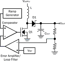
While this worked, it sometimes caused a ratcheting up of the inductor's magnetic field if the inductor current was not discharged sufficiently during the 'off' period of the PWM pulse. The natural results of this ratcheting effect were saturation of the inductor core, a significant jump in inductor current and, usually, catastrophic failure of the switching transistor.
As SMPS designs matured, designs moved toward a safer system known as current-mode. This system replaces the ramp generator with a current feedback signal that is driven by the inductor current. The result is a system in which the peak current in the inductor is directly controlled by the error signal, which eliminates the ratcheting of the magnetic field in the inductor and saves the life of countless transistors (see Figure 2).

This change to current mode brings with it another benefit: using the error voltage to control the maximum inductor current, which turns the inductor into a voltage-controlled current source. As a current source, the inductor no longer generates a pole in the frequency response of the loop. This changes the loop from unconditionally unstable to conditionally stable, which makes loop filter design much simpler.
Sampling rate: The current-mode control problem
So, if current mode is such a superior system, why are digital SMPS designs still using voltage mode? The answer is linked to the method used for monitoring the current feedback, and the speed needed for the required sampling rate.
For example, consider a 500 kHz system with 8 bits of PWM resolution. Using a voltage-mode configuration, the resolution of the PWM limits control of the pulse duty cycle to approximately 0,4% (100%/256). In addition, the voltage feedback will need to be sampled once per pulse, 500 000 samples per second, to provide the necessary input to the internal software-based loop filter.
Using the PWM duty-cycle resolution as a target, 256 conversions per PWM pulse are needed to achieve the same level of control. If the maximum duty cycle is 50%, then the ADC sample rate must be 256 million samples per second: 256/(2 mS x 50%).
Additionally, sufficient processing power is needed to gather these 256 million conversions, compare each to the error signal, and shutdown the PWM output when the desired current is reached. Conservatively, this means a processor with a minimum of 1 to 2 billion instructions per second (BIPS). With a 50% duty cycle, this means that half the processing power is tied up in just performing the cycle-by-cycle current limiting which is not a very cost-effective approach to this problem!
So, do designers have to just accept voltage mode in digital SMPS designs? The answer is no: there is an alternative.
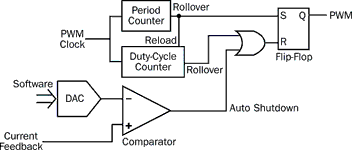
The alternative exists in using a microcontroller or digital signal controller (DSC) with a PWM peripheral onboard that works in the same way as a current-mode PWM generator (see Figure 3).
PWM peripherals to the rescue
The block diagram in Figure 3 shows two mixed-signal components, a voltage comparator and a digital-to-analog converter (DAC), added to a normal, timer-based PWM peripheral. The voltage comparator supplies a shutdown signal to the PWM module that is gated together with the output of the duty-cycle counter. The duty-cycle counter reaches zero, and the output of the comparator can now drive the PWM output to zero.
The DAC receives its input from the microcontroller and generates a reference signal into the comparator. When the system is built into a digital SMPS, the counters in the PWM module start the PWM pulse, the DAC generates a voltage at the inverting input to the comparator, representing the desired current in the inductor, and the current feedback is fed into the non-inverting input of the comparator.
As the current builds in the inductor, the duty-cycle counter continues to count down. If the inductor current reaches the desired level first, the comparator terminates the pulse and the inductor begins to discharge into the output capacitors. If the duty-cycle counter reaches zero first, then it terminates the PWM pulse. This gives the best of both worlds: a fast current-mode feedback that does not require a high MIPS processor, and the ability to set a maximum duty cycle for current limiting.
Another interesting feature is gained from this example. The resolution of the PWM duty cycle is only dictated by the counters in the event of a maximum duty-cycle termination. The voltage comparator shutdown is determined by the DAC's resolution, so the normal operating resolution of the PWM does not require a high frequency clock on the PWM peripheral.
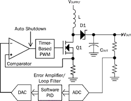
How is this system used? First, the PWM frequency and maximum duty cycle that the design requires are determined. These parameters are then used to configure the counter section of the PWM. Next, the reference DAC output is scaled to the expected maximum range of the current feedback signal. This provides the highest resolution in controlling the PWM duty cycle. Finally, the software proportional integrator differentiator (PID) is designed. This will take the voltage feedback from the analog-to-digital converter (ADC), compare it to the internal digital reference, filter it appropriately for stability, and then output the desired current setting to the DAC that is generating the comparator reference (see Figure 4).
Ensuring current-mode stability
But what about current-mode stability problems with duty cycles greater than 50%?
The PID software sets the required current level, so it is easy to scale the DAC value whenever the required current level exceeds half of the DAC's range. This makes implementing slope compensation in the digital world easier than in the analog world, because all that is required is software, while an analog solution requires a ramp-generator synchronised to the PWM pulse, as well as a summing junction in which the ramp adds to the current feedback.
The result of this process is a simple, current-mode SMPS system that uses less expensive, lower-MIPS processors to accomplish what a 1-2 BIPS processor does the hard way. Given that the processor only has to calculate a new desired current level before the start of the next pulse, the processor should have sufficient free time to accomplish other tasks including communications, system monitoring and deterministic functions such as soft-start/power-up sequencing, as well as handling fault detection and recovery. This also alleviates the need for a high-frequency PWM module. The high clock frequency was needed in voltage-mode digital SMPS designs to provide sufficient resolution in the duty cycle.
With the analog comparator auto-shutdown system, the resolution is dictated by the DAC's resolution, which provides the reference into the comparator. The only requirement on the clock frequency of the PWM is that it be high enough to accurately set the maximum current. For example, assume the same 500 kHz pulse with a maximum duty cycle of 60%. To achieve the resolution required for a 60% duty cycle, or 6/10 of the period, a counter of only 4 bits is needed. The resulting PWM clock frequency is only 5 MHz (10 x 500 kHz), which is a much more reasonable clock frequency than the clock required for a purely digital solution.
Sourcing the components for an analog comparator auto-shutdown system is easy. This type of peripheral has been available for several years, masquerading as a motor control device. The comparator shutdown mode was originally designed to provide protection for motors in the event of an over-current condition. In fact, there are even PWM generators in small 8- and 14-pin microcontrollers that have this auto-shutdown option. The only problem with small microcontrollers is their lack of a hardware multiply instruction, which is required for efficient PID function implementation.
Fortunately, manufacturers of DSCs have customers in the motor control markets, so there are currently quite a few parts with both a hardware multiply and the required PWM options. In addition, DSC manufacturers such as Microchip are beginning to generate new designs specifically targeted for digital SMPS. Most of these designs retain the comparator shutdown option on the PWM peripherals and, being DSCs, they include the necessary mathematical functions for efficiently processing PID algorithms.
The final result is the ability for digital SMPS designs to migrate into current-mode configurations with all the advantages inherent to both current-mode and digital control, without the prohibitive cost of high MIPS processors.
For more information contact Arrow Altech Distribution, +27 (0)11 923 9600, www.arrow.altech.co.za; Avnet Kopp, +27 (0)11 809 6100, www.avnet.co.za; Electrocomp, +27 (0)11 458 9000, www.electrocomp.co.za; Future Electronics SA, +27 (0)31 262 7743, www.futureelectronics.com; or Tempe Technologies, +27 (0)11 452 0530, www.tempetech.co.za
| Tel: | +27 11 923 9600 |
| Email: | [email protected] |
| www: | www.altronarrow.com |
| Articles: | More information and articles about Altron Arrow |
| Tel: | +27 11 458 9000 |
| Email: | [email protected] |
| www: | www.electrocomp.co.za |
| Articles: | More information and articles about Electrocomp |
| Email: | [email protected] |
| www: | |
| Articles: | More information and articles about Tempe Technologies |


© Technews Publishing (Pty) Ltd | All Rights Reserved
 printer friendly version