


There is a strong demand for systems that accurately measure counts, times and positions of objects falling in high speed and high rate in industries that make ball-bearings, chemical pellets, seeds, pharmaceuticals and other products.
Such systems can serve as tools to improve manufacturing processes, as well as aid quality control in these industries.
Previously developed techniques such as grease belt systems and LED/photodetector grids have been used to measure the distribution of falling objects. The limitation of grease belt techniques is that they do not take realtime measurements and they require extensive post-measurement processing.
Addressing the limitations of the grease belt technique, the LED/photodetector grid provides realtime, high-speed measurement, but suffers some critical shortcomings, such as poor spatial resolution limiting the capability to measure small objects (<4 mm), and the inability to resolve multiple objects when they appear too closely together and form a clump.
A machine vision-based system that uses one line scan camera has demonstrated better results than the grease belt and LED/photodetector grid methods, but the one-camera design did not solve the problem of distinguishing object clumps, or multiple objects that are too close and appear to be one object.
This case study describes a novel machine vision solution based on double line scan cameras and backlighting units. Special image processing algorithms were developed to identify, match, count and measure objects.
Challenged by John Deere, V I Engineering designed and developed a machine vision system that counts and measures falling objects in high speed and high density, using IEEE 1394 line scan cameras and backlighting units and incorporating specially developed image acquisition algorithms to identify and count objects, measure object time spacing and object XY coordinates. The system employed National Instruments' LabVIEW, the NI Vision Development Module and NI-IMAQ for IEEE 1394 in system development.
Vision system design
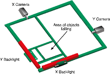
V I Engineering designed a machine vision system based on two line scan cameras and two linear backlighting units. One camera and one back illumination light are centred on the region of interest, or the area the objects fall through. Another pair of cameras and backlights is oriented perpendicular to the first pair. It is aligned such that the scan lines of both cameras and the centre lines of backlights are in the same plane (see Figure).
With the backlighting, each falling object appears as a black particle on a white background regardless of surface condition, brightness and colour of the falling object. This means that the vision algorithm does not need to be adjusted according to the appearances of the different objects. Two identical pairs of cameras/backlights are orthogonally placed, so that with the specially designed algorithm, they can measure the XY coordinates of the objects when they fall through the image plane.
The image plane is a virtual plane that is constructed by the two cameras' sensor lines and the linear backlights when they are properly aligned. A specially designed alignment fixture is used to align the camera sensor line's position and angle so that the line scan sensors and the two linear backlights are aligned in one image plane. The orthogonally oriented cameras provide another advantage over the one-camera configuration in that they allow the software to distinguish clump objects.
When multiple objects are very close spatially, they may appear as one single object in one camera image. However, from a perpendicular angle, the other camera most likely sees these objects as separate particles in the image. With a specially designed algorithm, this system is able to match and identify all the objects in two images and separate the 'clumped' objects.
Two IEEE 1394 line scan cameras with 1024 pixels from Imaging Solution Group were chosen for this application. Along with two linear lights manufactured by Advanced Illumination, the cameras provide object resolution of better than 1 mm in a 15 x 15 mm image area where all the falling objects are measured. The bright backlighting does provide a challenge for smaller objects by tending to make small objects not dark enough in the image, due to an edge diffraction effect that reduces the contrast of the small object. To overcome this, the threshold value was adjusted for smaller objects, enabling measurement of objects 1 mm or less in diameter.
The synchronisation of two cameras is critical to accurately counting and measuring falling objects. The cameras are externally triggered using a pulse train signal from an NI PCI-6601 counter/timer card. With this single-source triggering of the scanning lines and the precise physical alignment of the two cameras, an object appears in both camera images at the same vertical position.
One Dell PC was used to acquire and process images and run an object classification algorithm, as well as display, generate and report results. A NI PCI-8252 IEEE 1394 interface card plugs in to the PC and connects the two line scan cameras.
System performance
Spatial resolution and accuracy
1 mm ball bearings were used to test the minimum detectable object size of the system. The system can easily count and measure these ball bearings. Although tests have not actually been performed using objects smaller than 1 mm, it is predicted that it can resolve objects as small as 0,5 mm based on the current hardware configuration.
The accuracy of the spatial measurement is determined by the following factors:
* Image resolution.
* Camera sensor signal-to-noise ratio.
* Lens quality.
* Lighting quality.
* Optical calibration.
Time resolution and accuracy
The time resolution of the system is determined by the line scan rate of the camera and the speed of the image processing. In this system, the camera has a maximum line rate of 10 KHz, which translates to 100 microseconds of time spacing between scan lines. Because the cameras' line scan is triggered by an external precision pulse signal, the accuracy of the object timing measurement is mainly determined by the time resolution. It is estimated to be 200 microseconds.
Counting accuracy
With the current low-end system configuration, the system is able to count objects with variable sizes at up to 450 objects per second with 99% accuracy, whereas at the lower rate of 200 objects per second, the system has 99,5% counting accuracy.
The system specifications can be improved by using higher-performance components, such as cameras with higher line rate and more pixels, and frame grabbers with PCI Express technology. The machine vision system developed exceeds the original customer requirements and the customer has been using it successfully to improve the design and manufacturing processes of their products.
For more information contact National Instruments, 0800 203 199.


© Technews Publishing (Pty) Ltd | All Rights Reserved
 printer friendly version