


LEDs have developed greatly in recent years: from leading a niche existence as pure indicator lamps, to high-power LEDs with a light output currently exceeding 100 lumens. Lighting costs with LEDs continue to drop, and are predicted to soon reach pricing levels similar to those of classic cold cathode fluorescent (CCFL) lamps. This makes them of increasing interest for automotive lighting, as light sources in and on buildings, as well as for LCD panel backlighting in notebook PCs or televisions.
Advances in high-power LED technology have increased the importance of the thermal aspects in the design phase. Like all other semiconductors, LEDs must not be allowed to overheat, in order to avoid an accelerated degradation in luminescent output or, in the worst case, total failure. Although high-power LEDs have a higher efficiency than incandescent lamps, a high proportion of their power input nevertheless generates heat rather than light. Reliable operation thus demands good heat-sinking and taking into account expected ambient temperatures no later than during the design phase.
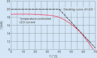
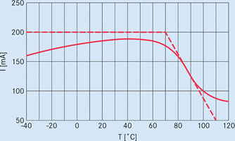
Thermal aspects must also be considered when designing the drive circuit of the LEDs: their forward current must be selected to ensure that the LED does not overheat, even at maximum specified ambient temperatures. This is done by reducing the maximum acceptable current as the temperature rises, a procedure known as derating. LED manufacturers include the derating curve in their specifications, similar to that shown in Figure 1.
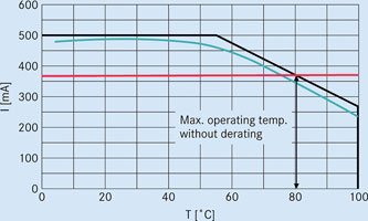
Operating an LED with a temperature-independent source of current such as a resistor has the disadvantage that at excessive temperatures the LED is operated outside of the specifications. Moreover, at low temperatures the light source is then provided with a current significantly below the maximum permissible current (see the red curve in Figure 1). Controlling the LED current by using PTC (positive temperature coefficient) thermistors in the LED driver circuit, results in a vastly improved operating curve similar to the green curve shown in Figure 1. This offers the following benefits:
* Increasing the forward current and thus the light output at room temperature.
* Cost savings, as the number of LEDs can be reduced, using less expensive driver ICs or even a driver circuit without integrated thermal management.
* The possibility of designing a driver circuit without IC control that is still able to vary the LED current dependent on temperature.
* The ability to use less expensive LEDs with more pronounced derating and a smaller safety reserve.
* Reliability is increased by the overheating-protection function.
* The thermo-mechanical design including heatsinks is simpler.
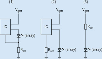
Most driver topologies for LEDs have the following in common: the forward current through the LED is set via a fixed resistor (Figure 2). As a rule, the current ILED flowing through the LED is inversely related to the resistance Rset ie, ILED ≈ 1/Rset. As Rset does not change with temperature, the LED current is also temperature-independent.
Thermal management of the LED current can be achieved by replacing the fixed resistor with a circuit that is temperature-dependent itself. The following examples illustrate how standard circuits can be improved with a PTC thermistor.
Example 1: constant-current source with a feedback loop
Circuit 1 in Figure 2 shows a frequently used driver topology. The constant-current source contains a feedback loop. The LED current is changed until the IC-specific feedback voltage VFB across the setting resistor at the feedback pin of the IC is reached. The LED current consequently sets itself at ILED = VFB/Rset.
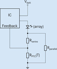
Figure 3 shows a modification of this circuit that generates a temperature-dependent LED current through a PTC thermistor. This circuit is matched to a special combination of driver IC and LED by the correct selection of PTC thermistor, Rseries and Rparallel. The LED current is calculated from the following equation:
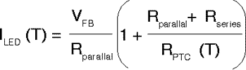
The graph shown in Figure 3 illustrates the resulting temperature dependence of the LED current. In comparison to a constant-current source dimensioned for a maximum operating temperature of 60°C, the LED current can be increased by up to 40% between 0°C and 40°C with a PTC thermistor and the brightness of the LED can be boosted by about the same percentage.
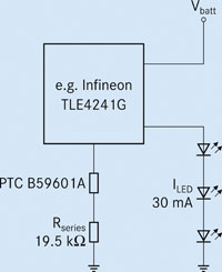
Example 2: Constant-current source with setting resistor not connected in series with the LED
Circuit 2 in Figure 2 shows another popular version of the constant-current source: the current is determined by a resistor connected to the driver IC. In this case, however, the setting resistor is not connected in series with the LED. The ratio between Rset and ILED is given in the IC specification. For example, using a series resistance of 20 kΩ, a driver IC of the TLE4241G type from Infineon Technologies results in an LED current of 30 mA. Figure 4 shows a modification of the standard circuit also containing a PTC thermistor. Although the PTC thermistor of Epcos' B59601A series used here has a resistance at 25°C of R25 = 470 Ω, at the sensing temperature, which can be set in 10°C-increments, the resistance of the component reaches 4,7 kΩ with a tolerance of ±5°C (standard series) or
±3°C (tight-tolerance series).
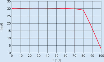
Figure 4 shows the resulting LED current as a function of the temperature. The narrowly toleranced fixed resistor Rseries dominates the total resistance at low temperatures. Only from about 15°C below the sensing temperature of the PTC thermistor does the current begin to drop due to its increasing resistance. A current of about 23 mA is reached at the sensing temperature (total resistance Rtotal = Rseries + RPTC = 19,5 kΩ + 4,7 kΩ = 24,2 kΩ). The steep rise of the PTC resistance at even higher temperatures leads quickly to shutdown and thus avoids heat death.
Example 3: Simple driver circuit without IC
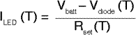
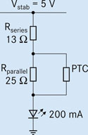
As circuit 3 in Figure 2 shows, LEDs can also be operated without a driving IC. This is illustrated by a circuit that drives a single 200 mA LED from an automotive battery. To avoid the fluctuations of the supply voltage, a voltage stabiliser generates a stable supply voltage Vbatt of 5 V. The LED is operated at Vbatt and the current set via a resistance element Rset connected in series with the LED. In this type of circuit, the temperature-independent forward current is obtained from the following equation, where Vdiode is the forward voltage of a single LED:
Alternatively, the fixed resistor can be replaced by a combination of a radial leaded PTC thermistor of the type B59940C0080A070 (R25 = 2,3 Ω) and two fixed resistors as shown in Figure 5. The resulting forward current is calculated with the equation:
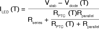
As a significant amount of the LED current flows through the PTC thermistor itself, a larger radial-leaded component was selected in this example. A significantly smaller chip PTC thermistor would heat up itself because of the current flowing through it and would always reduce the current independent of the ambient temperature. While connecting two or more chip PTC thermistors in parallel would divide the current, there are limits to this concept.
The current is essentially set to the desired value by suitable selection of the two fixed resistors. These resistors also play an essential role in improving the circuit by keeping the tolerance of the resulting LED forward current low. This is particularly important in the normal operating temperature range in which the PTC thermistor itself still has a wide resistance tolerance. The second parallel fixed resistor also ensures that the PTC does not switch the LED off completely even at extreme excess temperatures. So the current never drops below the value calculated from:
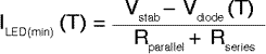
This property is extremely important in automotive electronics, for example, where the safety requirements do not allow the lights to be switched off completely.
For more information contact Electrocomp, +27 (0)11 458 9000, [email protected], www.electrocomp.co.za
| Tel: | +27 11 458 9000 |
| Email: | [email protected] |
| www: | www.electrocomp.co.za |
| Articles: | More information and articles about Electrocomp |


© Technews Publishing (Pty) Ltd | All Rights Reserved
 printer friendly version