


This article introduces the basic topologies and suggests good practical usage for ensuring stable operation of low-dropout voltage regulators (LDOs). We will also discuss design characteristics of Analog Devices' families of LDOs, which offer a flexible approach to maintaining dynamic- and DC-stability.
What are LDOs and how are they used?
Voltage regulators are used to provide a stable power supply voltage independent of load impedance, input-voltage variations, temperature and time. Low-dropout regulators are distinguished by their ability to maintain regulation with small differences between supply voltage and load voltage. For example, as a lithium-ion battery drops from 4,2 V (fully charged) to 2,7 V (almost discharged), an LDO can maintain a constant 2,5 V at the load.
The increasing number of portable applications has thus led designers to consider LDOs to maintain the required system voltage independently of the state of battery charge.
But portable systems are not the only kind of application that might benefit from LDOs. Any equipment that needs constant and stable voltage, while minimising the upstream supply (or working with wide fluctuations in upstream supply), is a candidate for LDOs. Typical examples include circuitry with digital and RF loads.
A 'linear' series voltage regulator (Figure 1) typically consists of a reference voltage, a means of scaling the output voltage and comparing it to the reference, a feedback amplifier and a series pass transistor (bipolar or FET), whose voltage drop is controlled by the amplifier to maintain the output at the required value. If, for example, the load current decreases, causing the output to rise incrementally, the error voltage will increase, the amplifier output will rise, the voltage across the pass transistor will increase, and the output will return to its original value.
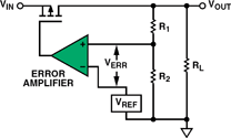
In Figure 1, the error amplifier and PMOS transistor form a voltage-controlled current source. The output voltage, VOUT, is scaled down by the voltage divider (R1, R2) and compared to the reference voltage (VREF). The error amplifier's output controls an enhancement-mode PMOS transistor. The dropout voltage is the difference between the output voltage and the input voltage at which the circuit quits regulation with further reductions in input voltage. It is usually considered to be reached when the output voltage has dropped to 100 mV below the nominal value. This key factor, which characterises the regulator, depends on load current and junction temperature of the pass transistor.
How are regulators distinguished by dropout voltage?
We can suggest three classes: standard regulators, quasi-LDOs, and low-dropout regulators (LDOs).
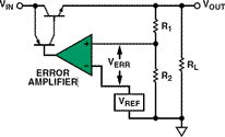
Standard regulators, which typically employ NPN pass transistors, usually drop out at about 2 V. Quasi-LDO regulators usually use a Darlington structure (Figure 2) to implement a pass device made up of an NPN transistor and a PNP. The dropout voltage, VSAT (PNP) + VBE (NPN), is typically about 1 V - more than an LDO but less than a standard regulator.
LDO regulators are usually the optimal choice based on dropout voltage, typically 100 mV to 200 mV. The disadvantage, however, is that the ground-pin current of a LDO is usually higher than that of a quasi-LDO or a standard regulator. Standard regulators have a higher dropout voltage and dissipation, and lower efficiency, than the other types. They can be replaced with LDO regulators much of the time, but the maximum input voltage specification - which can be lower than that for standard regulators - should be considered. In addition, some LDOs will need specially chosen external capacitors to maintain stability. The three types differ somewhat in both bandwidth and dynamic stability considerations.
How can I select the best regulator for my application?
To choose the right regulator for a specific application, the type and range of input voltage (eg, the output voltage of the DC-DC converter or switching power supply ahead of the regulator) need to be considered. Also important are the required output voltage, maximum load current, minimum dropout voltage, quiescent current and power dissipation. Often, additional features may be useful, such as a shutdown pin or an error flag to indicate loss of regulation.
The source of the input voltage needs to be considered in order to choose a suitable category of LDO. In battery-powered applications, LDOs must maintain the required system voltage as the battery discharges. If the DC input voltage is provided from a rectified AC source, the dropout voltage may not be critical, so a standard regulator - which may be cheaper and can provide more load current - could be a better choice. But an LDO could be the right choice if lower power dissipation or a more precise output voltage is necessary.
The regulator should, of course, be able to provide enough current to the load with specified accuracy under worst-case conditions.
LDO topologies
In Figure 1, the pass device is a PMOS transistor. However, a variety of pass devices is available, and LDOs can be classified depending on which type of pass device is used. Their differing structures and characteristics offer various advantages and drawbacks.
Examples of four types of pass devices are shown in Figure 3, including NPN and PNP bipolar transistors, Darlington circuits and PMOS transistors.
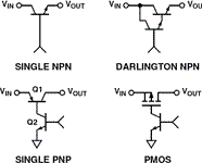
For a given supply voltage, the bipolar pass devices can deliver the highest output current. A PNP is preferred to an NPN, because the base of the PNP can be pulled to ground, fully saturating the transistor if necessary. The base of the NPN can only be pulled as high as the supply voltage, limiting the minimum voltage drop to one VBE. Therefore, NPN and Darlington pass devices cannot provide dropout voltages below 1 V. They can be valuable, however, where wide bandwidth and immunity to capacitive loading are necessary (thanks to their characteristically low ZOUT).
PMOS and PNP transistors can be effectively saturated, minimising the voltage loss and the power dissipated by the pass device, thus allowing low dropout, high-efficiency voltage regulators. PMOS pass devices can provide the lowest possible dropout voltage drop, approximately RDS(ON) x IL. They also allow the quiescent current flow to be minimised. The main drawback is that the MOS transistor is often an external component - especially for controlling high currents - thus making the IC a controller, rather than a complete self-contained regulator.
The power loss in a complete regulator is
PD = (VIN - VOUT) IL + VINIGND
The first part of this relationship is the dissipation of the pass device; the second part is the power consumption of the controller portion of the circuit. The ground current in some regulators, especially those using saturable bipolar transistors as pass devices, can peak during power-up.
How can LDO dynamic stability be ensured?
Classical LDO circuit designs for general-purpose applications have problems with stability. The difficulties stem from the nature of their feedback circuits, the wide range of possible loads, the variability of elements within the loop, and the difficulty of obtaining precision compensation devices with consistent parameters. These considerations will be discussed below, followed by a description of the anyCAP circuit topology, which has improved stability.
LDOs generally use a feedback loop to provide a constant voltage, independent of load, at the output. As is true for any high-gain feedback loop, the location of the poles and zeros in the loop-gain transfer function will determine the stability.
NPN-based regulators, with their low-impedance emitter-loaded output, tend to be relatively insensitive to output capacitive loading. PNP and PMOS regulators, however, have higher output impedance (collector loaded in the case of the PNP). In addition, the loop's gain and phase characteristics strongly depend on the load impedance, thus requiring special consideration for stability.
The transfer function of PNP- and PMOS-based LDOs has several poles that impact stability:
* The dominant pole (P0 in Figure 4) is set by the error amplifier; it is controlled and fixed, in conjunction with the gm of the amplifier, through an internal compensation capacitance CCOMP. This pole is common to all of the LDO topologies described above.
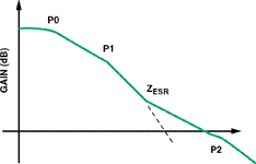
* The second pole (P1) is set by the output elements (the combination of the output capacitance and the load capacitance and resistance). This makes the application problem more difficult to handle, as these elements affect both the loop gain and bandwidth.
* A third pole (P2) is due to parasitic capacitance around the pass elements. PNP power transistors have a unity-gain frequency (fT) much lower than that of comparable NPN transistors, under the same conditions.
As Figure 4 shows, each pole contributes 20 dB/decade of rolloff in gain, with up to 90° of phase shift. As the LDOs discussed here have multiple poles, the linear regulator will be unstable if the phase shift at the unity-gain frequency approaches -180°. Figure 4 also shows the effect of loading the regulator with a capacitor, whose effective series resistance (ESR) will add a zero (ZESR) into the transfer function. This zero will help to compensate for one of the poles and can help to stabilise the loop if it occurs below the unity-gain frequency and keeps the phase shift well below -180° at that frequency.
ESR can be critical for stability, especially for LDOs with vertical-PNP pass devices. As a parasitic property of a capacitor, however, the ESR is not always well controlled. A circuit may require the ESR to fall within a certain window to ensure that the LDO operates in the stable region for all output currents (Figure 5).
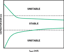
Even in principle, choosing the right capacitor with the right ESR (high enough to reduce the slope before the frequency response crosses through 0 dB, yet low enough to bring the gain below 0 dB before the associated pole, P2) can be challenging. Yet the practical considerations add further challenges: ESR varies, depending on the brand; and the minimum capacitance value to use in production will require bench tests, including extreme cases with minimum ambient temperature and maximum load.
The choice of the type of capacitor is also important. Perhaps the most suitable are tantalum capacitors, despite their large size in the higher capacitance ranges. Aluminium electrolytics are compact, but their ESR tends to deteriorate at low temperatures, and they do not work well below -30°C. Multilayer ceramic types do not have sufficient capacitance for conventional LDOs (but they are suitable for anyCAP designs, read on).
Analog Devices' anyCAP family of LDOs
LDO implementation is considerably easier now, thanks to improvements in both DC and AC performance associated with regulators employing the Analog Devices anyCAP LDO architecture. As the term implies, regulators embodying it are relatively insensitive to both the size of the capacitor and its ESR, thus allowing for a wider possible range of output capacitance.
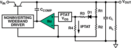
The approach has spread and is now more widely available in the marketplace, but it may be helpful to understand how this architecture (Figure 6) simplifies the stability issue.
The anyCAP family of LDOs, including the 100 mA ADP3307 and the 200 mA low-quiescent-current ADP3331 can remain stable with output capacitance as low as 0,47 mF, using good-quality capacitors of any type, including compact multilayer ceramic. ESR is essentially a nonissue.
The simplified schematic of Figure 6 shows how a single loop provides both regulation and reference functions. The output is sensed by the external R1-R2 voltage divider, and fed back to the input of a high-gain amplifier through diode D1 and the R3-R4 divider. At equilibrium, the amplifier produces a large, repeatable, well-controlled offset voltage that is proportional to absolute temperature (PTAT). This voltage combines with the complementary temperature-sensitive diode voltage drop to form the implicit reference, a temperature-independent virtual band-gap voltage.
The amplifier output connects to an unusual non-inverting driver that controls the pass transistor, allowing the frequency compensation to include the load capacitor in a pole-splitting arrangement based on Miller compensation. This provides reduced sensitivity to value, type and ESR of the load capacitor. Additional advantages of the pole-splitting scheme include superior line-noise rejection and very high regulator gain, thereby providing exceptional accuracy and excellent line and load regulation.


© Technews Publishing (Pty) Ltd | All Rights Reserved
 printer friendly version