


In Europe, the performance of electrical and electronic equipment in railway applications is governed by two international standards. The one most frequently cited in design specifications is the document IEC571, 'Electronic Equipment on Rail Vehicles', also known as European Norm EN50155, 'Electronic Equipment Used on Rolling Stock Equipment'. In the UK, the standard that applies is RIA12, 'General Specification for Protection of Traction and Rolling Stock Equipment from Transients and Surges in DC Control Systems', developed by the Railway Industries Association (RIA). While these two standards are similar in most respects, the RIA12 standard also requires a specific surge withstanding capability.
The following discussion shows how to comply with these standards using Vicor modular DC-DC converters to facilitate the design of complex power supplies.
Electrical requirements for EN50155 (IEC571)
Operating voltage ranges
Table 1 lists the nominal input voltages (VN) provided by power sources used for railway applications.
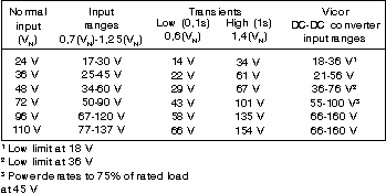
Equipment powered directly from batteries with no voltage stabilising device must function properly with input voltages that range from 0,7 VN to 1,25 VN during normal operation. The equipment must also withstand input voltage drops of 0,6 VN for 100 ms and overvoltage surges of 1,4 VN for one second that may occur during startup.
Table 1 shows that, with some exceptions, standard Vicor DC-DC converters cover all of the specified input ranges and transients.
Fast transient specification
Equipment must be able to withstand a direct transient of 1800 V lasting 50 μs. The impedance of the transient source is specified as 100 Ω, with transient energy around 100 mJ. To prevent damage to the DC-DC converter, the module must be connected to a suppression device, such as a transient voltage suppressor (TVS), directly across the input. A TVS able to withstand up to 1,5 J would be suitable. The TVS's clamping voltage must be selected so that it will not exceed the high line voltage or transient limits of the converter.
RIA12 surge protection
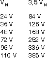
The RIA12 standard specifies that equipment must withstand a 20 ms over-voltage surge 3,5 times greater than the nominal voltage. To meet this standard, a suppression circuit must be used with the DC-DC converter.
For each of the standard input voltages, the maximum input surges are as follows:
Since the source impedance of this overvoltage pulse is 0,2 Ω, a common clamping device, such as a TVS, will not provide a suitable solution because the energy dissipated would be:
Instead, an active circuit as shown in Figure 1 is necessary.
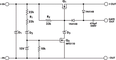
In this circuit, D1 clamps the fast, high voltage spikes, while the active part formed by D2, D3 and Q1, Q2 limits the surge. During normal operation, Q1 is kept in full conduction by the charge pump circuit made up of the 1N4148 diodes and the 470 pF capacitor. The GATE OUT signal from the converter drives the charge pump.
When overvoltage occurs, the diode D2 conducts, with current limited by R1, and turns Q2 on. With Q2 in conduction, the gate voltage of Q1 is held to the clamping voltage of D3. The output voltage equals the clamping voltage of D3 minus the gate source voltage of Q1. When overvoltage ceases, the system resumes normal operation.
Component selection
The components in Figure 1's circuit remain essentially the same for all input voltage ranges. Only the main MOSFET Q1 and the clamping diodes D1, D2 and D3 are selected according to nominal operating voltage and power. To select Q1 it is necessary to consider the values of 3,5 VN and the operating current IN, as well as the SOA limits for a single 20 ms pulse. The RDS(on) must also be taken into account, since the power dissipation under normal operating conditions is calculated as
P = RDS(on) • IN²
The diodes D2 and D3 can have the same breakdown voltage, in which case the output (clamped) voltage will equal D3 minus the gate source voltage.
The RIA12 standard prescribes an input voltage variation of up to 1,5 VN for one second. For converters with an input voltage range that allows the module to withstand this, the breakdown voltage for D2 and D3 must be greater than 1,5 VN to prevent the protection circuit from operating under this condition, but less than the converter's high line voltage.
The diode D1 clamps high voltage spikes that have low energy but amplitudes that may exceed 1000 V. Therefore, D1 must be a TVS with a clamping voltage higher than 3,5 VN to prevent damage by this transient.
Test results
This circuit has been tested in the lab for 48 V and 110 V inputs - the two most common in railway applications - supplying a 150 W DC-DC converter. Table 2 lists the components used.
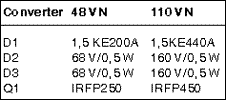
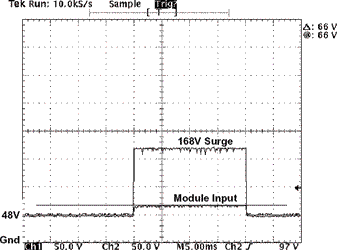
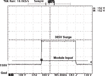
Figures 2 and 3 show the 20 ms input transient and the output voltage clamped to the converter's high line limit.
In general, these circuits prove effective in suppressing high energy voltage surges. They are flexible enough to be adapted to suit applications besides those needing to meet RIA12 requirements.
Physical requirements
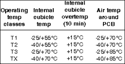
Operating temperature range
Operating temperatures are divided into four classes according to the severity of the environment, as shown in Table 3. When designing the power supply, it is necessary to consider over-temperature during start-up, indicated in the third column.
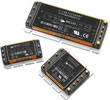
In some railway applications, the equipment is bulkhead mounted on the wagon walls. This setup can take advantage of the Vicor converters' planar baseplate and use the cabinet as a large heatsink.
Vibration and shock
EN50155 specifies that electronic equipment mounted on boards and boxes fixed to the vehicle frame must be able to withstand vibration on all three axes at the following levels:
* Frequency range: 5-150 Hz.
Cross-over frequency: 8,2 Hz.
* Displacement amplitude (below cross-over frequency): 7,5 mm.
Acceleration amplitude (above cross-over frequency): 20 m/s².
The equipment also must be able to withstand a 50 ms, semi-sinusoidal shock of 50m/s² amplitude. Because they are fully encapsulated in epoxy resin, Vicor modules can sustain these mechanical stresses; however, close attention must be paid to the PCB design and wiring to prevent relative movements that can stress the modules' pins.


© Technews Publishing (Pty) Ltd | All Rights Reserved
 printer friendly version