


Since the approval of the recommendations set forth by the Institute of Electrical and Electronics Engineers (IEEE) 802.3af task force in 2003, Power over Ethernet (PoE) equipment vendors have been designing standards-based products that leverage the numerous advantages offered by PoE.
To date, product deployments have included Voice over IP (VoIP) phones, wireless access point (WAP) devices, IP network security cameras, and other devices capable of eliminating external power supplies in favour of accepting data plus power via the Ethernet connection. Carrying the promises of scalability, ease of installation and the flexibility to deploy PoE devices in hard-to-access locations, PoE has rapidly become the preferred technology for enterprise networks seeking speed of installation, cost savings, power management and higher reliability for these connections.
Today, as PoE equipment vendors begin to introduce enhanced products to feed the demands of organisations that desire greater functionality from their PoE devices, the power required to drive these new products is also on the rise. The IEEE 802.3af standard sets the transmission guidelines for PoE at 15,4 W (and at least 12,9 W per port at the endpoint). But new product introductions, such as cameras with motorised zoom and tilt capabilities, require more power to operate than the IEEE 802.3af standard allows. This need for more power resulted in the decision to begin work on a new standard.
In September of 2005, the IEEE launched a task force to begin reviewing new PoE specifications in order to enhance the IEEE 802.3af guidelines into a next-generation standard, IEEE 802.3at, referred to as PoE Plus. The goal for the new standard is to increase available power delivery up to at least 30 W (optionally up to 60 W) to provide greater power for evolving applications. The IEEE 802.3at standard will be backward compatible with all existing IEEE 802.3af devices such that commonly deployed VoIP phones, WAPs and IP network security cameras will operate on PoE Plus ports. While PoE Plus ports must be backward compatible with standard PoE, new PoE Plus endpoint devices will be required to identify themselves as such in order to draw additional power over these ports.
As work progresses on the IEEE 802.3at standard, questions have begun to circulate regarding compliance towards the new standard and what infrastructure components may be necessary. Will current structured cabling be able to handle the increase in power? Are there additional considerations for heat rise in bundled cables?
Power over Ethernet standards
The telecommunications industry was built around 48 V powering standards. IEEE 802.3af is the first international standard to define the transmission of PoE. One of the recommended implementations for PoE is shown in Figure 1. This standard is based on existing category 5 infrastructures as a baseline requirement to support: (1) voltage supply between 44 and 57 V DC; (2) 350–400 milliamperes; and (3) 15,4 W of power at the source. Category 5 (and higher) Ethernet cabling is capable of supporting these PoE devices in today's infrastructure up to 100 metres (90 metre horizontal + 10 metre patch field).

In order to achieve higher power for new endpoint devices, the PSE will be required to drive between 50 and 57 V. For example, to deliver 42 W to an endpoint device at 50 V, the maximum current per Ethernet pair required is 0,840 A. The power dissipated can then be calculated as: 840 mA/2 = 420 mA per wire such that (0,420 A) x (0,420 A) x 10 Ω = 1,764 W/wire or (1,764 W/wire) x 4 wires (assuming two pair powering) = 7,056 W of power dissipated in the cable.
How does it work?
PoE as defined by today's IEEE 802.3af standard supports 15,4 W at the source distribution point via the power sourcing equipment (PSE) which can be PoE switches, PoE midspans or PoE enabled patch panels. The minimum supplied voltage must be 44 V such that the current per twisted Ethernet pair is calculated from:
Amps = Power/Volts
So today, the maximum required current per Ethernet pair is 15,4 W/44 V = 0,35 A.
To calculate power dissipated as heat in the Ethernet cable we need to calculate the effect on each wire. Using the 350 mA from above yields 175 mA per wire. Power dissipated is calculated as:
Power Dissipated = Amps² x Resistance
Assuming 10 Ω resistance per wire (worst case over 100 metres), the power dissipated per wire = (0,175 A) x (0,175 A) x 10 Ω = 0,306 W. However, since we have two wires per pair and utilise two pairs (send/return) we must calculate the total power dissipated for the Ethernet cable as 0,306 x 4 or 1,224 W per cable.
Who is concerned?
The IEEE formed the Data Terminal Equipment (DTE) Power Enhancements Task Force to enhance the existing 802.3af standard and to provide maximum power to endpoint devices within practical limits, including providing cable heating data for evaluation by the IEEE 802.3an (10GBASE-T 10 Gbps) working group.
The Telecommunications Industry Association (TIA) formed the Technical Recommendation (TR) 42 Premises Telecommunications Cabling Engineering Committee, which under the TR-42.7.2 Copper Cable working group is responsible for developing performance specifications, qualification procedures, and test methods for copper twisted-pair cable.
The International Standards Organisation (ISO) and International Electrotechnical Commission (IEC) under ISO/IEC JTC 1/SC 25/WG 3 committees are concerned with customer premises cabling and specifically monitoring and setting parameters for radiated emissions, signal spectrum and immunity on 10/100/1000 and 10GBASE-T cabling. Each of these committees and task forces cooperates with each other to advance cabling standards and recommendations for new services such as PoE Plus over Ethernet cable.
Temperature's importance
For PoE and PoE Plus, the condition to be monitored is the temperature rise above ambient room (or enclosure) temperature related to the cable or cable bundles transporting power. The following factors can affect temperature rise:
1. Amount of current passing through the cable.
2. Resistance per length of cable.
3. Number of cables in the bundle carrying current.
4. Power being carried on two pairs or four pairs within these cables.
The IEEE 802.3at task force has established a requirement for Category 5e, Category 6 and Category 6a cabling to ensure the resistance characteristics and the quality of transmissions. The TIA is recommending that the maximum heat rise is less than 10°C. This temperature rise will affect the cable performance slightly by increasing insertion loss by approximately 0,4% per degree of heat rise. A 10°C increase would require an approximate 0,35 dB greater performance margin or a shorter cable length.
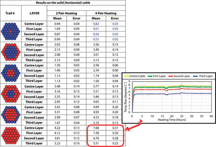
The above tests were performed for both 2-pair powering and 4-pair powering modes. Of significant interest is the ambient heat rise of approximately 7°C on the centre cable in a fully powered 37-cable bundle. The performance tests indicate that even with all cables powered, ambient heat rise does not exceed the 10°C maximum established by the TIA TR-42 recommendation. Category 5e cabling is the lowest category as required by the IEEE 802.3at task force and performs well, as the test results in Figure 2 indicate, when carrying powering on all 4-pair and all 37 cables in a bundle (the most strenuous of tests).
Looking to the future
PoE carrying 30 to 60 W will be able to support significant new devices ensuring infrastructure support for emerging technologies. New devices will also be released that consume less power, making the ubiquitous PoE port capable of connecting to a greater variety of devices. For example, laptop manufacturers, in an effort to reduce power consumption, may replace motorised disk drives with more efficient and less hungry memory arrays. Also, as LED display panels become more popular, the ability to increase the size and number of pixels (LED points) will be a function of the amount of sustained power available.
Mixed mode installations of low to medium powered devices combined with higher power devices will balance the power required on customer premises cabling installations. These installations will certainly allow PoE and PoE Plus to be deployed across all ports in the local area network.
For more information contact Michael Pula, Panduit, [email protected]


© Technews Publishing (Pty) Ltd | All Rights Reserved
 printer friendly version