


LEDs have emerged in recent years as viable sources of light and are no longer used solely as status-light indicators for electronic equipment. Advances in technology have provided LEDs that are typically three times more efficient than incandescent bulbs. LEDs are also extremely durable and have lifetimes exceeding tens of thousands of hours.
Power LEDs for lighting applications are designed to be driven with a constant current source. It is common to see standard current-drive levels of 350 mA and 700 mA among different LED manufacturers. The forward voltage across the LED can, however, vary depending on the type and number of junctions connected in series. Many manufacturers of power LEDs will provide multiple junctions, integrated into a single module.
One simple method that can be used to drive an LED is to install a resistor, in series, to limit the current. A linear voltage regulator or operational amplifier (op-amp) circuit can also be connected in a constant-current configuration. However, these linear methods will not have enough efficiency at the required power levels.
A switch-mode power supply (SMPS) provides a much more efficient solution for driving the LED. An SMPS can buck or boost the input voltage to the correct level, to provide the desired LED current. The system input-voltage range and the required LED forward voltage will determine the SMPS topology that is selected.
Buck-boost converter
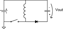
The buck-boost converter topology is used when the supply voltage may be above or below the required output voltage and is especially useful for battery applications. This topology is also known as a flyback or inverting regulator.
A buck-boost converter can be implemented as shown in Figure 1. This implementation has the advantage that a simple, low-side MOSFET driver circuit can be used. The topology shown in Figure 1 will generate a positive voltage, referenced to the input-voltage rail. The down side of this buck-boost implementation is that the load is not referenced to the circuit ground.
LED-driving with an MCU
A simplified circuit design for an LED driver is shown in Figure 2, using a mixed-signal, high-voltage, 8-bit microcontroller such as Microchip's PIC16HV785. The output of the circuit is referenced to the battery voltage, not to ground. The output of the inverter is connected to the LED anode and produces a voltage that is greater than the input voltage.
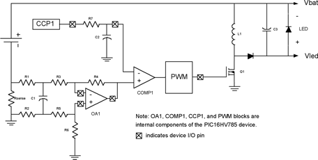
The PIC16HV785 mixed-signal microcontroller combines an 8-bit core with several on-chip analog peripherals. These include a high-speed two-phase PWM circuit, ideal for current-mode control of SMPS, and two on-chip op-amps that can be used to amplify the voltage across the current-sensing resistors. This allows the use of very small sensing resistors, which reduces circuit losses and increase overall efficiency. The on-chip high-voltage shunt regulator eliminates the need for an external 5 V regulator when operating from higher supply voltages. The PIC16HV785 also integrates a digital capture, compare and PWM (CCP) module, two analog comparators, a 10-bit A-D converter, an 8 MHz internal clock circuit, internal precision voltage reference, and a programmable brown-out reset (BOR) circuit.
All of the pins of the op-amps and comparators are externally accessible, so that any circuit configuration can be implemented.
Current sensing
The current-sensing op-amp is connected as a differential amplifier, to obtain an accurate measurement of the voltage across the current-sense resistor. The current is measured in the return of the power source, to simplify the requirements of the circuit. R1, R2 and C1 form a low-pass filter to reduce any switching noise that may be present. The cutoff frequency of this filter must be chosen above the converter switching frequency, to avoid limiting the control-loop response.
Current regulation
The two-phase PWM module, an internal comparator and a voltage reference form the circuit that regulates the amount of LED current. The two-phase PWM is an analog-style module that works on the set/reset principle. First, a clock signal, derived from the system clock, is used to periodically turn on the PWM output. The PWM clock signal sets the fundamental PWM frequency. Then, a reset signal from one of the on-chip comparators turns off the PWM output, when a specified reference level has been reached.
The amplified current signal is internally routed to the positive input of Comparator 1 on the PIC16HV785. The Capture-Compare Peripheral (CCP1) is used in the PWM mode to generate the voltage reference for the comparator. Using the PWM allows fine control of the comparator reference voltage. The PWM signal is filtered with an RC filter to produce an analog voltage and is connected to the negative comparator input pin.
Software implementation
The software for this application is very simple, since the LED current control function is accomplished in the analog domain. After all peripherals have been enabled and a current-reference level has been set, the LED will continue to illuminate without software intervention.
However, the application code can use the on-chip 10-bit A-D converter to measure the supply voltage which then drives the LED in a constant-power mode. As the battery input voltage changes, a new voltage reference value is produced by the D-A circuit (implemented with the CCP peripheral) to provide the required compensation.
Setting LED brightness
Since the microcontroller core is only spending a small portion of time in the power-regulation process, more time can be dedicated to the user interface and to provide additional features, such as battery status monitoring and brightness level control. There are two ways that the LED light level can be adjusted using this circuit and software.
The first technique relies on the principle that the brightness of the LED will change with the drive current. In fact, an approximate linear control of the LED brightness can be accomplished using this method. However, variable-current dimming is not the most efficient way to set the LED brightness level, since the LED achieves its best efficiency at the maximum drive-current level specified by the manufacturer.
A low-frequency PWM signal of between 60 Hz and 1000 Hz can be used to modulate the LED drive current. Instead of reducing the current-drive level, the LED is always driven at maximum current during the on-time. The duty cycle of the PWM signal sets the average amount of time that the LED is energised. The chosen PWM frequency should be sufficiently high so that the LED current is turned on and off at a rate that will not cause the human eye to detect flickering. The PWM frequency must also be low enough so that the current-regulation circuit has enough time to stabilise during the PWM on-time. If these conditions are met, the human eye will average the light output from the LED over time.
Summary
The PIC16HV785 contains all the required components to implement an efficient high-power LED drive circuit. It can be easily configured for boost operation or buck-boost operation, depending on the input-voltage range. The application uses only a small portion of the microcontroller's RAM and Flash memory, leaving plenty of room for additional the application code. With enough unused peripherals on the PIC16HV785, a second LED driver, battery charger, or other switch-mode circuit can also be implemented.
| Email: | [email protected] |
| www: | |
| Articles: | More information and articles about Tempe Technologies |


© Technews Publishing (Pty) Ltd | All Rights Reserved
 printer friendly version