


Despite different sounding predictions, processor speeds and transfer rates of computer systems have increased more and more in recent years.
With processors this has mainly been achieved by distributing the computing performance to several processor cores. Hand in hand with this development, the performance loss and thereby the demand for cooling has increased still further. The MicroTCA standard therefore contains an entire article devoted solely to the cooling of a MicroTCA system.
Parameters from the MicroTCA standard
Forced air cooling is used here as the cooling method. The performance losses of the individual AdvancedMC modules are defined, from 20 W for a Single Compact AdvancedMC module up to 80 W for a double full-size module. Various cooling configurations are presented, the air distribution in a slot is defined, and barometric changes due to differing heights and sea level are also pointed out. Air filters, thermal sensors and many other details are specified.
With air alone: push or pull
The system architect only has one aim: to observe the defined parameters of the standard and to guarantee sufficient air flow to the individual AdvancedMC modules.
There are two basic methods: the push and pull principles.
With the push principle the fan is positioned in front of the AdvancedMC modules and expels the air through the slot. The advantage of this principle is that the fan with its motor and necessary electronics is located in the cold air intake of the system. The fan components themselves are therefore sufficiently cooled and have a higher life expectancy. On the other hand the fan motor does generate heat which is blown into the board cage, thus raising the base temperature.
With the pull principle the fan is positioned behind the board cage and sucks the warm air out. Therefore the heat generated by the fan motor does not influence the temperature inside the board cage. The fan motor and the fan electronics, however, are exposed to the hot air generated by the AdvancedMC modules. The operating temperature of these components is therefore considerably higher and will thus shorten their life expectancy.
Management for cooling
A speciality of MicroTCA is the management concept. Each AdvancedMC module, Power module and also the fans have to be provided with a management controller. The MicroTCA carrier hub (MCH) takes over the control of the individual management building blocks.
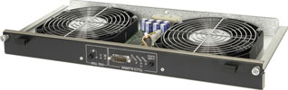
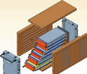
MicroTCA defines so-called cooling units (CU). One or two of these coolings units can be in a system, with each unit consisting in turn of one or several fans. One cooling unit should be sufficient for the cooling requirements of the system, with the optional second cooling unit arranged as a redundant component. Following this definition it is sensible, with redundant cooling, to use both principles described above and place one cooling unit in front of the AdvancedMC modules and the other behind them. This solution is then called the push/pull principle. To facilitate an exchange of fan units it makes sense to arrange them as plug-in units (Figure 2), which can easily be exchanged from the front.
As a shelf manager, the MCH takes over the task of regulating the temperature in the system during cooling. The AdvancedMC modules assembled in a MicroTCA system (eg, CPUs) are equipped with individual logic and temperature sensors. If the temperature exceeds the defined parameters, this information is signalled as an ‘event’ to the shelf manager. The shelf manager then gives the command to the cooling unit to adjust the fan speeds accordingly.
Vice versa, the cooling unit reports the status of the fans, as well as possible failures and malfunctions to the shelf manager, thus achieving a very high guarantee against operating failure.
Such an intelligent fan control has several advantages. Firstly, the life expectancy of the fans is increased, as the speed is adjusted to the required performance of the MicroTCA system. On top of this, the noise level is reduced with reduced speed and electrical energy is conserved.
With air and water
With AdvancedTCA, a performance loss of 200 W per blade was defined. But some of today’s applications already exceed these limits. There are applications which require up to 300 W per board. The same can be expected for MicroTCA. There will be future applications which will exceed the limit of 80 W. At some stage heat expulsion with pure air cooling will no longer be possible.
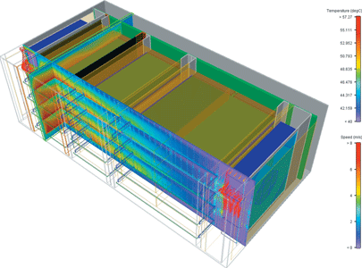
The result of such developments will be the use of other cooling principles, which are mostly based on fluids. Applied on cabinet and subrack level (Level I and II in accordance with DIN IEC 62454), this leads to the use of air/water heat exchangers (LWWT), that take over the task of cooling the hot air which has been generated by the MicroTCA components. The functionality principle of such an LWWT is based on two cycles separated from each other.
The internal air cycle circulates the air inside the cabinet, whereby the heat energy generated by this is being transported to the heat exchanger, from where it is transported further on to a chiller (cold water replacement) via the external cycle with a suitable fluid (mostly pure water, but it could also be a non-conductive fluid, such as Fluorinert FC-77). With Schroff’s LHX 20 air/water heat exchanger, up to 25 kW of heat loss per cabinet can be dealt with. The heat exchanger has a closed cycle (air flow volume 1000 to 3000 m³/h) and operates with an environmental temperature of 5°C to 70°C and a relative humidity from 5 to 85%. Assembled at the side, the heat exchanger with its separation elements guarantees the cooling of all systems assembled in the cabinet.
On the systems level (Level III in accordance with DIN IEC 62454), fluid is solely used for the cooling of ‘hot spots’, ie, the neuralgic points on the boards (Figure 3). For this a specific, fluid cooled cooling element is assembled onto the critical component. The inlet and outlet pipes for the cooling unit are connected to the chiller with totally drip-free couplings.
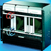
Such couplings can be assembled at the front or the rear, whereby the front assembly presents two basic disadvantages: firstly, valuable space is used up on the front panel, secondly, each time a board is extracted it has to be decoupled manually first. With couplings assembled at the rear, they are automatically decoupled or connected when extracting or inserting a board.
With water only
If the remaining elements on the board are still air cooled, this is termed hybrid cooling; otherwise pure fluid cooling (liquid cooling) is used. For this, Schroff has developed special frame-type plug-in units (Figure 4), which can be integrated into subracks and in which boards with particularly critical components can be cooled with a so-called ‘cold plate’.
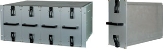
These cold plates consist for instance of aluminium with grooves, into which the copper or stainless steel pipes are pressed. Therefore, normal tap water can be used for the cooling. Adjusted to the performance loss and the geometric requirements each cold plate is configured specifically for the customer application. The plates/pipes can be configured for a volume of 2 to 16 l/min. The electronic components are assembled customer specifically on both sides of the cold plate.
The intake and outlet of water is realised via a coupling plate, located at the rear of the subrack. During the insertion of the frame-type plug-in unit into the subrack, electrical contact is established as usual. At the same time the connection to the coupling plate is realised via drip-free fast couplings. These are configured in a suspended manner, so that possible variances in X and Y can be balanced. Despite their small dimensions, they guarantee high flow rates in both directions and are configured to approximately 1 million cycles and a maximum operating pressure of 450 bars. Depending on the temperature range, the use of different sealing materials is possible: Nitril (NBR, -15 to +100°C), Fluor carbon (FPM, -10 to +150°C) or Ethylene-Propylene (EPDM, -20 to +150°C).
Water only for ruggedised applications
In the second quarter of 2007, a PICMG working group was formed, which is working on the MicroTCA standard MicroTCA.1 ‘Rugged MicroTCA’. The aim of this standard is to adapt MicroTCA for rugged environments, as they are found in railway and transport technology, traffic technology, manufacturing, security and defence technology.
In particular for applications in outdoor areas, high IP protection is often demanded. IP56 protection and higher, require hermetic sealing of the system from the outside world, making conventional air cooling impossible. The heat has to be transported from the hot spots on the AdvancedMC module to the outside of the system, without water, dirt or anything else being able to penetrate the system.
To fulfil such demanding requirements, the greatest care is being taken when it comes to perfect contacting between the hot spots and the enclosure. This is realised via an aluminium module plug-in unit, inserted into the AdvancedMC module (Figure 5).
A milled aluminium part, which touches the surface of the processor on the AdvancedMC module, is connected to this plug-in unit. This transfers the heat from the processor to the module plug-in unit via the milled aluminium part, which itself is pressed into the grooves in the top and base plate of the board cage by means of a wedge lock.
Via this full surface contact, the heat from the module plug-in unit is transferred to the system parts of the board cage. Therefore, only the outer side of the system has to be cooled. This can for instance be realised with cooling fins, in order to improve the heat exchange with the environment. Another possibility would be to use cold plates instead, so that the heat which is transferred to the top and base plate can be dissipated with the cold plates.
| Tel: | +27 11 608 3001 |
| Email: | [email protected] |
| www: | www.actum.co.za |
| Articles: | More information and articles about Actum |


© Technews Publishing (Pty) Ltd | All Rights Reserved
 printer friendly version