Circuit protection using PTC resettable fuses
29 October 2008
Circuit & System Protection
Information from Bourns
It is frequently necessary to separate a part of a circuit from the power source while maintaining the integrity of the remaining circuit in a working status. In instances where a part of a system could be damaged and the remaining section will need to continue to operate, the following circuit design, employing a PPTC (polymetric positive temperature coefficient) resettable fuse is an option.
In this example application, a series of circuits are attached to the secondary side of the transformer or single bus bar from the power supply. The total resistance of each circuit branch is calculated using the algebraic form of Ohm’s law (voltage = resistance x current.) Typically, the inductance and capacitance are negligible when compared to the overall impedance of the device. In series, the resistance is added directly.
Figure 1.
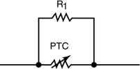
R(T) = R1 + R2
(Calculation 1)
Resistances in parallel are added using the parallel resistance formula R(T) = 1/((1/R1)+(1/R2)) where R(T) is the total resistance of the two resistors in parallel. R1 and R2 (see Figure 2) are the values of the resistors in the parallel circuit.
Figure 2.
R(T)= 1/((1/R1) + 1/(R2))
(Calculation 2)
A Bourns Multifuse PPTC device can be chosen depending on the value of each branch resistance and the voltage applied – see Calculation 3 and Figure 3. With the known voltage of the power supply and the calculated value of the branch circuit, we can determine the current of the branch. For the branch at node one, the calculated resistance is 8 Ω. We then determine the current using the voltage of 24 volts and Ohm’s law. The current is 3 amps, so we choose the MF-R300. In the same way, the value of current at node 2 is determined to be 2 amps, so the MF-R200 is chosen.
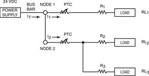
Figure 3.
R(T1) @node 1 = R1 + RL1 = 8 O
R(T2) @node 2 = 1/((1/(R2 + RL2)) + (1/(R3 + RL3)) = 12 Omega;
V = IR
V = I1 (R1 + RL1) = I1 8 O V = 24 V d.c.
24 V d.c./8 O = 3 Amps = I1 @ node 1
V = IR</b>
V = I2 R(T2) = I2 12 Omega; V= 24 V d.c.
24 V d.c./12 O = 2 Amps = I2 @ node 2
The Ihold for the PPTC device R1 at Node 1 will be 3 amps, so an MF-R300 will be chosen
The Ihold for the PPTC device R2 at Node 2 will be 2 amps, so an MF-R200 will be chosen
I(T) for the circuit will be I1 + I2 = 5 amps. So the Imax over current rating of the PPTC is not violated.
(Calculation 3)
If the overall resistance is calculated (see Calculation 2), the current can be solved by using Ohm’s law. The overall current calculation should equal the sum of the current at node 1 (I1) and node 2 (I2) where I(T) = I1 + I2.
If there is a short circuit at load RL2, the current, which is the same current through the MF-R200 at node 2 (R2), will rise. As this occurs, the I2R will also rise. As the I2R rises, the resistance of the PPTC will rise exponentially. According to Ohm’s law, as the resistance rises, the current will drop sharply.
This will not affect the circuit at node 1. The current will be blocked from node 2 until the fault condition is removed and the PPTC is reset through thermal radiant dissipation. The entire resistance of node 2 becomes exponentially high, causing I2 to go towards 0 amps. Thus the total current I(T) = I1.
Further reading:
Safety relay for explosive areas
IOT Electronics
Circuit & System Protection
Phoenix Contact has expanded its safety portfolio with the new PSR-MC35-EXI safety relay module, specifically engineered for use in potentially explosive environments.
Read more...
Clearing the Static: Ensuring effective ESD control
Actum
Circuit & System Protection
To maintain reliable electrostatic discharge control, regular testing and accurate measurement are essential, with grounding products and ESD testing equipment being vital.
Read more...
Clearing the Static: The importance of ESD audits
Actum
Circuit & System Protection
An ESD audit is the first step in establishing an effective static control programme in the workplace, and will help identify vulnerable areas and potentially hazardous static zones that require improvement.
Read more...
EMI shielding materials application guide
Circuit & System Protection
TE Connectivity’s shielding solutions include electrically conductive elastomers, gaskets, knitted wire mesh, oriented wire, EMI shielding ventilation panels, shielded window, cable shielding and shielding components.
Read more...
Clearing the Static: ESD containers and packaging
Actum
Circuit & System Protection
Vacuum forming ESD
Electronic components can be damaged by electrostatic discharges. To protect against such damage, electronic assembly parts are often transported or stored in vacuum formed component
...
Read more...
Electrostatic discharge chairs
Actum
Circuit & System Protection
An ESD chair forms an integral part of grounding within the electrostatic discharge protected area to prevent potential damage to products.
Read more...
Conductive ESD footwear
Actum
Circuit & System Protection
Conductive ESD footwear is used in conjunction with other grounding devices, such as a wrist strap, cord, and ESD surface mats, to provide a continuous path to ground.
Read more...
Clearing the Static: The importance of cleaning in ESD control
Actum
Circuit & System Protection
To prevent Electrostatic Discharge (ESD) damage to sensitive electronic assemblies and components, all production, handling, packaging, and storage must take place in an ESD-protected environment.
Read more...
Clearing the Static: Staying grounded
Actum
Circuit & System Protection
To maintain reliable electrostatic discharge control, regular testing and accurate measurement are essential, with grounding products and ESD testing equipment being vital.
Read more...
Smarter protection without disruption
NewElec Pretoria
Circuit & System Protection
Designed for operations still running without integrated automation, NewElec’s retrofit-friendly systems let you upgrade performance and safety without overhauling your entire network.
Read more...


 printer friendly version