


There is no such thing as a universal power LED driver circuit.
In reality, different power LED applications can have very different technical requirements. And there is a wide choice of components available, at a wide range of prices, to meet these requirements.
In other words, the decision over the choice of a driver circuit for a lighting application is complex, and has reference to many variables. To help the design engineer avoid the waste of time and effort involved in evaluating different power topologies through trial and error, this article elaborates a systematic method for choosing the right topology in the light of a clear and simple set of application parameters.
The key considerations that have to be borne in mind in order to reach the right decision are:
* What is the power source (AC mains, low-voltage DC, battery or other)?
* What is the relationship between the input and output voltages?
* What is the range of voltages required in the system?
* What is the power requirement?
* Is isolation required?
* Is dimming required?
* Does the supply have to power multiple channels (for instance in RGB colour-mixing applications)?
* What are the EMC constraints?
* What is the bill of materials budget?
A decision tree leading from the particular conditions of a circuit to a topology and component type that best meets the demands of the application provides a valuable first level of discrimination between the various methods for powering LEDs – see Figure 1. The design engineer will still have choices, between topologies (in some cases) and between components (in all cases). Then, secondary features, such as an IC’s ability to provide pulse width modulation (PWM) control, can make one device preferable to another.
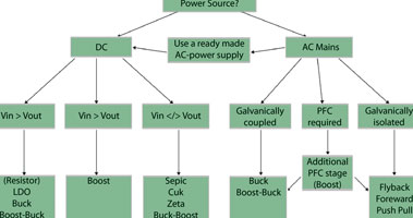
But it is essential to productive design that the first high-level choice – that of topology – is right.
The unusual challenges in powering lighting systems
The design engineer faced with the specification for a power LED system could be forgiven for thinking they have been given an impossible mission. On the one hand, the power circuit must deliver a steady, high power output at very high efficiency (system-level efficiency is one of the main selling points of the latest generation of power LEDs.)
On the other hand, a tight bill of materials (BOM) budget nearly always applies. The LED itself is generally replacing a much cheaper conventional light source; there is therefore very strong pressure on the engineer to ensure that the power circuit does not add to the cost disadvantage of the power LED system.
It gets worse: power semiconductor manufacturers have thrived for many years in a market that demanded many flavours of constant-voltage regulator. As a result, there are thousands of such devices readily available at very competitive prices.
Unfortunately, these cheap and useful products are not geared to the needs of the lighting circuit designer, who must deliver a constant-current output, not a constant voltage. Power IC manufacturers are moving quickly to meet the very fast-growing demand for LED drivers, but many devices target particular applications or requirements. This can endow them with features or specifications that might not be optimised for general use.
LED power circuits: factors to consider
As Figure 1 shows, the first factor to consider when deciding on a driver topology is the kind of power source that is to be used. Next is the ratio between input and output voltages. It is in general simple to match the current and voltage ratings of a power IC to the specification of the circuit. These ratings come into sharper focus at relatively high values, however, where a controller with external switches can become necessary.
Options within and beyond the decision tree
As can be seen, the decision tree in Figure 1 provides a useful guide to ensure the designer avoids building prototypes using a topology that is clearly unsuited to the task. But how is the designer to make the choice between different topologies when the decision tree points to more than one candidate?
This is where the constraints of power LED system design come into play – the balancing of features (such as flexible PWM control) and efficiency against BOM cost.
This can best be illustrated by reference to a specific application example. Consider an application in which the designer has the flexibility to choose the input voltage. In this instance the resistor can be ignored; theoretically it could be used here, but it is a crude approach to the problem and provides no regulation. This leaves the choice of three more or less simple topologies.
A linear driver such as the NUD4001 from ON Semiconductor gives excellent current regulation and creates no electromagnetic emissions. Linear drivers are also simple to use and cost little. A linear driver can operate very efficiently provided the voltage overhead can be kept low and the LEDs’ forward voltage stays within tight tolerances.
This second requirement, however, is not straightforward – power LEDs with a binned forward voltage are hard to get and the cost is higher. If the end application has a medium-to-high production volume, it is invariably not possible to source LEDs from a single bin. In addition, a linear driver can dissipate only a moderate amount of power; in practice, the NUD4001 can drive at most two power LEDs.
So what if the application uses more than two LEDs, and/or there is a large difference between the input and output voltages? In this case, a switching topology is more appropriate, as it is a more efficient way of handling varying circumstances.
Two topologies offer a simple implementation: the buck topology and the boost topology. Both offer high efficiency over a wide range of electrical parameters. Both also create electromagnetic emissions, which need to be managed in order to comply with EMC regulations.
The two topologies achieve their effect in different ways, and these differences affect the efficiency with which they operate. In the buck topology shown in Figure 2, the LED is in series with the inductor. This means that only a fraction of the energy has to pass through the inductor, the component which contributes a significant part of the losses. In this topology, the average current through the inductor is no more than the current through the LED.
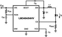
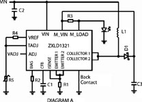
In the boost configuration, all the energy passes through the inductor, as it is charged to ground and then discharged through the LED, averaged by a capacitor. In addition, the current through the inductor is higher than the current through the LED; losses increase with the square of the current. In practice, in a circuit with comparable power output, a typical boost regulator such as Zetex Semiconductors’ ZXLD1321 in Figure 3 will deliver around 85% efficiency versus around 95% for a typical buck converter such as the LM3404 from National Semiconductor in Figure 2.
Conclusion
There is not, then, one ‘best’ driver circuit for power LEDs. Lighting designers are now learning to experiment with the new possibilities afforded by solid-state lighting, but already it is perfectly clear that the highly standardised form factors and uniform light outputs of traditional incandescent lamps are going to be replaced by a rich variety of new luminaire types using the small size and easy controllability of LEDs to do many new things with light.
Power circuits will reflect this diversity, and for the engineer tasked with designing them, a familiarity with the various potential power topologies will be essential.
For more information contact Marian Ledgerwood, Future Electronics, +27 (0)21 421 8292, [email protected], www.futureelectronics.com
| Tel: | +27 21 421 8292 |
| Email: | [email protected] |
| www: | www.futureelectronics.com |
| Articles: | More information and articles about Future Electronics |


© Technews Publishing (Pty) Ltd | All Rights Reserved
 printer friendly version