


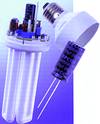
Aluminium electrolytic capacitors used in compact electronic ballasts for fluorescent lamps must withstand high ripple currents and extreme operating temperatures over a long service life. For these heavy-duty applications, Epcos developed the B43858 series of single-ended capacitors.
Higher luminous efficacy and longer service life make fluorescent lamps ideal for large-scale replacement of incandescent lamps. Their efficiency can be improved by a further 10 to 20% with electronic ballasts. Operating at high frequencies, electronic ballasts offer numerous advantages over conventional magnetic ballasts, such as reduced flicker and strobe effects, low audible noise, reduced weight and size, and dimming capability.
Electronic ballasts call for aluminium electrolytic capacitors of high reliability. They must be able to handle extreme ripple currents with high and low frequency components, and have a long service life. In some cases, the capacitors are even exposed to high surge voltages. The Epcos B43858 single-ended capacitor series have passed endurance tests of 5000 h at 105°C. They feature high reliability and ripple current capability with a specified service life of at least 50 000 h.
Electronic ballasts without power factor correction
Electronic ballasts without power factor correction are mainly used in low-power applications such as energy-saving lamps. An example of this topology is shown in Figure 1.
Capacitor C2 is used directly as a filter for the rectified voltage. It is exposed to a low-frequency ripple-current component during charging and a high-frequency component during discharging. The rectifier diodes have a very small conduction angle because the capacitor is charged at very short intervals at maximum voltages. The frequency is 100 or 120 Hz, depending on line frequency (50 or 60 Hz). As a result of short current pulses with a high harmonic component in the input, this circuit has a relatively low power factor of 0,5 to 0,7. The waveform of the input current is shown in Figure 2.
The capacitor is normally discharged via the switching transistors at a frequency determined by the oscillator circuit, typically in the range from 20 to 100 kHz.
Another characteristic of this circuit is that any voltage surges from the AC line must be directly absorbed by the filter capacitor. This problem can be solved by using an input filter with varistors (Figure 3), which not only protects the circuit against overvoltages, but also suppresses electromagnetic interference caused by the high frequency of the switching stage.

An input filter of this design is essential for compliance with VDE, UL and FCC requirements. Epcos also offers a wide range of components for filter chokes, ferrite materials for transformers and varistors.
In circuits without the input filter, the aluminium electrolytic capacitor should be designed for a rated voltage of 350 or 400 V (input voltage 220 V) or 250 V (input voltage 110/127 V). If an input filter with overvoltage protection is used, a capacitor designed for 200 V is sufficient. However, the maximum input voltage variation should first be determined.
In some special cases with an input voltage of 110/127 V, the circuit should be designed as a voltage doubler as shown in Figure 4.
Each capacitor is then charged during a half-cycle, which increases ripple current. The result is a waveform similar to that just described. The ripple current of the capacitor must be carefully calculated here because there are large low-frequency components of 50 or 60 Hz. The rated voltage of the capacitor should be 250 V in circuits without the line filter, 200 V in those with the line filter.
Electronic ballasts with power factor correction
In electronic ballasts with power factor correction, an active harmonic filter is used between the rectifier diodes and the filter capacitor Figure 5.
The filter consists of a control circuit, which regulates the voltage across capacitor C10 by turning inductor L1 on and off via transistor Q1. As the clock frequency is much higher than the frequency of the AC line, the input current and input voltage of the ballast are approximately in phase. The harmonic component is therefore very low, so that the power factor approaches unity. This circuit eliminates high voltage pulses in the charging circuit and low-frequency current components in the filter capacitor. The driver circuit for the lamp is similar to that used in circuits without power factor correction. The waveform of the input current is shown in Figure 6.
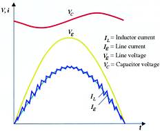
Thanks to the active harmonic filter, any voltage surges in the AC line will not affect the capacitor. A line filter for suppression of electromagnetic interference is still required for compliance with VDE, UL and FCC requirements. The capacitor used in this circuit should be designed for a rated voltage of 400 or 450 V.
Calculating capacitor parameters
Correct calculation of the parameters of the aluminium electrolytic capacitor for the filter is essential to successful design of electronic ballasts. The following criteria must be considered:
* Rated voltage - The rated voltage of the capacitor should match the circuit. Thanks to special high-density papers of high dielectric strength, aluminium electrolytic capacitors of series B43858 can withstand surge voltages up to 10% higher than the rated voltage.
* Ripple current - The capacitance selected should be based on the ripple current in the application and the service life of the circuit. The service life of the aluminium electrolytic capacitor is mainly determined by the operating temperature, which is the sum of the ambient temperature and self-heating of the capacitor. Self-heating is in turn determined by the ohmic losses resulting from the capacitor's equivalent series resistance (ESR), which should be as low as possible over the entire frequency range. Epcos capacitors of series B43858 feature a special etched anode foil with a large surface area that ensures high conductivity in the electrolyte. They thus combine high ripple current capability with long service life. When the ballast operates under heavy load, the ambient temperature is particularly high at that point on the circuit board where the capacitor is located. Components that generate heat, such as switching transistors, should therefore be kept as far away as possible from the capacitor.
* Mechanical design - Single-ended aluminium electrolytic capacitors have an internal structure designed for optimum volumetric capacitance. They are available in a wide range of sizes with capacitances up to 68 µF for 450 V in cans measuring 20 x 40 mm. A new product line with reduced dimensions, eg 16 x 15 mm, is available for ballasts of low-profile design. In addition to types with standard terminal configurations (bulk, cut, preformed), single-ended capacitors can be supplied with special polarity reversal protection for added safety. Here one of the terminal pins is flattened and broader, so that the capacitor can be mounted on the board in one position only. Capacitors up to 16 mm can also be supplied taped on reels for automatic placement.
Summary
Single-ended aluminium electrolytic capacitors of the new B43858 series from Epcos are ideal for heavy-duty applications such as electronic ballasts. Insulation made of special high-density papers ensures high dielectric strength while a special etched anode foil with a large surface area results in high conductivity of the electrolyte. Ripple current capability and equivalent series resistance (ESR) have been optimised for high frequencies, reliable performance and long service life. For special applications, custom versions can be developed on request.
| Tel: | +27 11 458 9000 |
| Email: | [email protected] |
| www: | www.electrocomp.co.za |
| Articles: | More information and articles about Electrocomp |


© Technews Publishing (Pty) Ltd | All Rights Reserved
 printer friendly version