


Lately the three-level neutral-point-clamped (NPC) topology known from high-power applications is also being applied in low- and medium-power applications to exploit specific advantages in system level design.
Applications requiring filters, like UPS systems or PV inverters, benefit from improved spectral performance and lower specific switching loss of lower voltage class devices. Up to now, setting up a three-level phase leg has only been possible by applying discrete devices or combining at least three modules. By integrating a three-level phase leg into a single module, adapting chip technology for slightly higher breakdown voltage and providing a simple solution for driving this topology becomes more appealing for new projects.
Operating principles of 3-level NPC topology
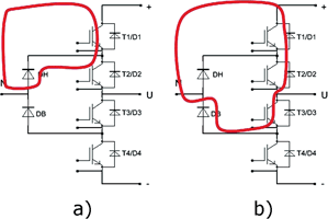
The three-level phase leg in NPC topology consists of four IGBTs with their associated anti-parallel diodes, all arranged in series, and two additional diodes – DH and DB – connecting intermediate nodes to the neutral point of the DC-link. All power semiconductors used exhibit the same blocking voltage. Depending on the polarity of output voltage and current, four different commutation loops are in operation during one period of the output base frequency.
With voltage and current in the positive direction, T1 and DH operate like a buck chopper whereas T2 just conducts the output current without switching as shown in Figure 1a). For negative voltage and current, T4 and DB operate like a boost chopper with T3 just conducting the current. For these conditions only two devices are within the commutation loop and this will be referred to as short commutation. But with the output current being negative combined with positive voltage, current flowing through T3 and DB has to commutate to D2 and D1 as shown in Figure 1b). This commutation involves four devices and will be designated as long commutation. For the remaining case (positive output current, negative voltage) another path of long commutation exists. Managing stray inductances and over-voltages for the long commutation is one of the most demanding tasks when designing three-level converters.
New IGBT modules optimised for 3-level NPC topology
While integrating a total of four IGBTs and six diodes is not an option for high-power applications, this is feasible in the low-power and medium-power ranges as far as the number of available power and control pins permits the use of a standard package.
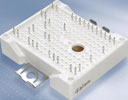
For the low power range, the EasyPACK 2B package as shown in Figure 2 offers sufficient DBC area to integrate a complete 150 A three-level phase leg. Since pins can be placed freely within the given grid and the pins can be assigned to provide either a power or a control function, suitable interconnection means are provided. There are auxiliary emitter terminals available to enable fast switching. For power terminals, up to eight pins are used in parallel to achieve the required current rating as well as to minimise stray inductance and PCB heating.
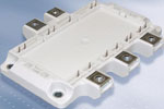
For the medium power range, the EconoPACK 4 package is an optimal choice for integrating all the power devices. The three terminals are used to enable a low inductance connection to a split DC-link as it is needed for three-level converters, whereas the two terminals on the opposing side are used in parallel as phase output terminals. A driver PCB can be connected directly to the control terminals visible at the edge of the module frame. This package is intended to be used for three-level phase legs with chip currents up to 300 A.
Integrating all devices of a three-level phase leg into one module is very promising in regard to minimising stray inductance, but with only 600 V of blocking voltage it is still very difficult to meet typical application requirements due to non-perfect balance of DC-link voltages and faster switching of 600 V devices.
To ease the design and give customers larger margin, these modules are equipped with enhanced IGBT and diode chips which can block 650 V. These new chips have exactly the same conduction and switching characteristic as the well known 600 V IGBT3 devices; the robustness of both devices (SOA, RBSOA, SCSOA) also remains unchanged. This is enabled by the development of new termination structures for IGBT and diode, ensuring that the thickness of 70 μm is not changed. Therefore, VCESat of the 650 V IGBT stays at its value of 1,45 V at 25°C (1,70 V at 150°C) [1] with low switching losses that contribute only one third of the total inverter losses for switching frequencies of 16 kHz. The IGBT also retains its smooth current tail that even at critical conditions shows no snap-off [2]. The diode also stays at the optimised VF-Qrr trade-off of 1,55 V at 25°C (1,45 V at 150°C) [1] and keeps its soft switching behaviour.
The challenge of IGBT driver design for 3-level topology
The application of three-level NPC topology in low- and medium-power applications creates some specific driver requirements that have to be considered for optimum system performance.
Arising from high switching frequency
Due to switching frequencies covering a range from 16 kHz to 30 kHz, the driver has to provide a small and consistent propagation delay so that the dead time can be minimised. Considering the fast switching times of 650 V devices, the main contribution to dead time requirement arises from variation in driver propagation delay [3]. If dead time is too large compared to the period of the switching frequency, this will lead to nonlinear behaviour of the inverter stage, creating new challenges in control algorithms [4], [5].
Arising from topology
Although the devices used only have a blocking voltage of 600 V or 650 V, the isolation requirements for the driver are similar to a 1200 V application. Since the number of driver circuits doubles, it is mandatory to use a design for the driver and its power supply with low part count and low board space requirement. Protection features like short circuit detection and under-voltage lockout have to match with three-level NPC topology. Turning off an inner IGBT first (T2, T3 in Figure 1) would expose this device to the full DC-link voltage and lead to immediate device failure due to SCSOA or RBSOA violation.
With the new integrated IGBT drivers of the EiceDRIVER family these requirements can be met comfortably [6], [7]:
The integrated microtransformer provides basic isolation up to a repetitive isolation voltage of 1420 V peak.
With the integrated Active Miller Clamp feature this driver can be used with a single supply at high switching speed without the risk of parasitic turn-on [8].
Compared to typical optocoupler based drivers, tolerances and variation of propagation delay are significantly reduced by the microtransformer technology.
The integrated VCESat protection may be used for the outer switches, but has to be disabled for the inner IGBTs.
Laboratory test and results
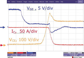
The following discussion is based on the switching waveforms of an EasyPACK 2B 3-level module. The tests were done using the 1ED020I12-F gate driver for the IGBTs. The current was measured with current transducers either at DC+ or DC-.
Short commutation
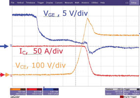
Figure 4 shows the switching waveforms of a short commutation at nominal current, a DC voltage of 400 V and 25°C junction temperature. As shown, with a peak value of 550 V the voltage stays well within limits.
Long commutation
Figure 5 shows the switching waveforms of a long commutation under the same conditions. With a voltage peak of 580 V this voltage is only about 30 V higher than for the short commutation and still well below the 650 V breakdown voltage.
First measurement results show that with integration of a complete three-level phase leg into a single module, switching behaviour similar to short commutation can be achieved for long commutation. However, to achieve enough headroom to switch at higher currents, a further reduction of circuit stray inductance would be necessary. This can be achieved easily by using several capacitors in parallel and using a multilayer board, reducing the spacing between the coplanar power layers connecting module and capacitors. Furthermore, it has to be considered that a real application circuit would not contain current transformers within the DC-link connections. The current transformers used here contribute to stray inductance with 15 nH, increasing the over-voltage by 45 V.
Conclusion
By integrating a complete phase leg into a single module, increasing blocking voltage from 600 V to 650 V and providing a highly integrated driver solution, the three-level inverter proves to be an attractive candidate for low- and medium-power low-voltage applications requiring high switching frequency, filtering and high efficiency like double conversion UPS and PV inverters.
References
[1] Datasheet of FS6R06VE3_B2, available at www.infineon.com
[2] Kanschat, P.; Rüthing, H.; Umbach, F.; Hille F.: 600 V IGBT³: A detalied analysis of outstanding static and dynamic properties, Proceedings of ISPSD.
[3] Infineon Technologies AG: AN 2007-04, How to calculate and minimise dead time requirement for IGBTs properly, May 2007.
[4] Holmes G.; Lipo, T.: Pulse width modulation for power converters, IEEE Press, Piscataway, 2003.
[5] Kalker, T.; Ackva A.; Jansen, U.: Novel digital controller for induction machines considering the inverter switching times and a fluctuating DC-link voltage, EPE 1991, Vol. 2, p. 58-62.
[6] Strzalkowski, B; Jansen, U.; Schwarzer, U: High performance IGBT-driver in microtransformer technology providing outstanding insulation capability, PCIM 2007.
[7] Infineon Technologies AG: Datasheet 1ED020I12-F, October 2008, available at www.infineon.com
[8] Infineon Technologies AG: AN 2006-01, Driving IGBTs with unipolar gate voltage, Dec. 2005, available at www.infineon.com
For more information contact Davis Moodley, Infineon, +27 (0)11 706 6099, www.infineon.com


© Technews Publishing (Pty) Ltd | All Rights Reserved
 printer friendly version