


Vapour phase soldering (VPS) has been around in the industry for many years and was one of the only two serious options during the early introduction of surface mount technology. In the early days engineers had the option of brown belt for single sided products, infrared and VPS.
The first reflow system used by this author was VPS, preferring the simplicity of the process and process setup over the problems of accurate loading, board/belt positioning, profiling and overheating of paste causing flux residue charring.
A well designed board works very well and gives high soldering yields. A poor design – particularly on passive components – will amplify the number of lifted and tombstoned components. All vapour phase systems can show a difference in component lift due to the fundamental nature of the process but with the degree of control/flexibility offered today, even marginal design can produce good yields. As vapour condenses on the surface of the board and turns to liquid which encases the whole assembly, component movement can occur.
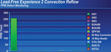
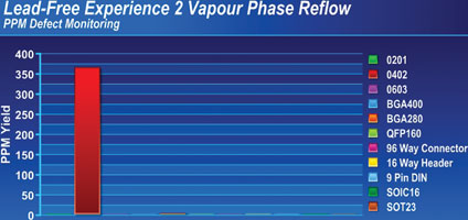
In a vacuum assisted unit, poor control of the rate of pressure change can also make a nice mess of assembled parts. Is this a reason to dismiss VPS? No, it is often just an excuse to stick with the poor design. It is simple and quick to change footprints by a few mils, so the design should be updated when one orders a new batch of boards. A recent lead-free trial comparing VPS with convection for a client showed an increased number of lifting defects with VPS. If one only looked at the total PPM levels one may say that VPS was the reason, but the defects were all on one component size (0402) – hence the need for good documentation during NPI design reviews.
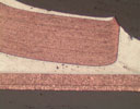
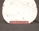
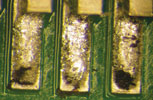
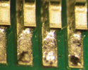
One lead-free process defect which has been apparent with a number of lead-free trials on 0201 chip resistors/capacitors and small chip-scale packages is not seen with VPS. When soldering boards with a wide range of other components including QFP, BGA and through-hole connectors there can be a large delta-T. To optimise the process and decrease delta-T, the surface of the board – including very small paste deposits – will often be at elevated temperatures, just below reflow, for long periods. This can cause flux exhaustion prior to reflow, leaving incomplete coalescence of all the solder balls as shown in Figure 3. With modern VPS this does not occur but it could happen with old VPS processes when using a secondary vapour layer.
There is no argument that VPS soldering provides a better wetting performance with tin/lead and lead-free alloys and on different solder finishes when compared to air convection. However, the results can become blurred when compared with nitrogen convection. It is often stated that VPS soldering is an inert soldering process and that is true when the board assembly enters the vapour layer. Prior to that, or when the board in some designs is not in a vapour during cooling, this may not be the case. Wetting balance measurements of boards subjected to reflow cycles in VPS do show changes in wetting after the first reflow cycle but not to the same degree as with convection reflow in air.
Vapour phase as a process has always been around as an option in the industry and there will be new engineers that select the process. There will also be existing engineers who will move back from convection to VPS as a solution for lead-free. It was interesting two years ago to listen to development staff of a major machine supplier discuss where noticeable improvement in convection technology could come from. There are areas of cooling and energy savings still to be achieved, but was a re-launch of VPS the solution?
It can be seen that it is perfectly feasible, by using more than one vapour phase system, to carry out sequential soldering processes at different temperatures. This may be a benefit to some companies and often for non PCB applications. Due to the high cost of the liquids necessary, it is clearly imperative that the design of the machine that is to be used with these fluids should be maximised in terms of not allowing vapour or fluid loss from the system. This also means that the PCB design should not have, for instance, any fluid traps which could carry this extremely expensive fluid out of the system. It should be remembered that the only reason for the secondary layer on older machines was a ‘sacrificial blanket’ to prevent the loss of the primary vapour. In the batch and in-line vapour phase systems of today, systems do not have a secondary vapour blank.
From a profiling point of view the goal is to solder joints with the minimum delta-T across the board and at the lowest peak temperature. It is vital to minimise the time joints are in a liquid state and control the speed of temperature rise to reflow. Gone are the concerns of damage of the boards due to excessive temperatures. Care does need to be taken on fixturing of small or light boards on carriers. If they are lost into the boiling sump there is no way to retrieve them until the fluid cools. In the case of designs which employ a heated plate to vaporise the fluid as opposed to the traditional sump systems, retrieval may be easier but still not recommended.
In the original batch vapour phase system the primary fluid was boiled, generating a vapour layer. In order to contain this vapour within the size constraints of the holding tank, it was necessary to cover the vapour to prevent it escaping, and this was done with a secondary fluid which also produced a vapour layer boiling at a lower temperature. The condensing coils used cold water running through them at a very low flow rate to recondense the vapour; the fluid then circulated back through filters. Above the primary coil another coil was used to reduce the loss of the secondary blanket of vapour sitting on top of the primary fluid.
In operation, a basket loaded with assembled boards would simply be lowered through the secondary layer and into the primary. Prior to reflow the boards were often preheated in a separate oven to obtain a step heating process, reduce the collapse of the vapour and prevent the secondary vapour condensing on the board assembly. After the work had reached reflow temperature, the basket would be raised. On the way up, it was allowed to dwell in the secondary blanket, in order to contain primary vapour and fluid. Ideally the board or basket would be very slightly angled to allow condensed fluid to run off. The basket would then be raised out of the machine and allowed to cool.
There are still differences in the delta-T on the board surface and under components but it is very small at the peak temperatures provided the time is allowed for the profiles to converge. The initial temperature rise through preheat does have recordable differences just like convection, but can be smaller depending on the machine design and the effort put in by the engineer to optimise the process.
For more information visit www.ASKbobwillis.com


© Technews Publishing (Pty) Ltd | All Rights Reserved
 printer friendly version