


It is notoriously difficult for designers to anticipate the field reliability of new products before they are issued to the market.
Obviously at that point, if there is an unexpectedly high level of field failures, then the answer is clear and the designer has failed. However, if there are never any field returns, this begs the question: has the designer over-engineered the product? What is required is a way to take the guesswork out of design by eliminating the cost penalty for built-in product reliability.
Often the most critical system element, in terms of reliability, is the power supply. Failure of the power supply usually results in a system shutdown, but there could be more far-reaching consequences. If the power supply failure causes subsequent damage to the load, the cost of failure could be far greater than that of the power supply itself.
The power supply is in a vulnerable position because it is directly connected to the AC mains, which is a highly energetic system that is outside of the designer’s control. The mains can, from time to time, be subject to power surges and incidences of dangerous high-voltage spikes and transients. The load itself could develop a fault and generate an overload or short circuit condition. Cooling fans could become blocked or obscured, and the whole system could overheat.
The power supply design engineer must achieve performance specifications and cost targets while ensuring ruggedness and reliability. This can be an extremely difficult task when faced with component tolerances, production variables and the many hazards to be addressed. However, the evolving sophistication of power control ICs is making it easier for the design engineer to sleep at night. This can be illustrated by considering a design example, in this case a flyback converter using a TOPSwitch-HX controller/power IC produced by Power Integrations.
TOPSwitch-HX incorporates a 700 V power MOSFET, high-voltage switched startup current source, multimode PWM controller, oscillator, thermal shutdown circuit, fault protection and other control circuitry in a single monolithic device. The combination of many features into a single device enables a complete functional power supply to be designed with only a small number of external components.
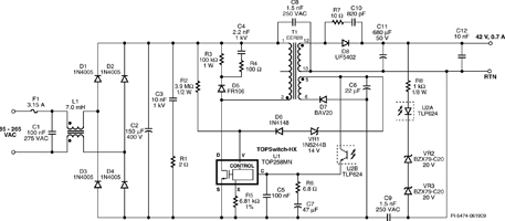
Figure 1 is a design for a complete switch mode power supply suitable for use in printers and light industrial applications employing motors or actuators. The power supply is specified to deliver a constant 30 W at 42 V and a peak loading of 84 W without an external heatsink. The peak loading capability feature of this circuit allows it to deliver the high currents required for motor startup from components sized to support a continuous load. This provides a significant size, cost and weight advantage without compromising reliability.
The TOPSwitch-HX (U1) incorporates user-defined protection features to avoid damage to the power supply and load in the event of line under-voltage, over-voltage and output overload conditions. The thermal shutdown feature is auto-recovering and an auto-restart function protects against output short circuits and open feedback loops. The implementation of these protection features is discussed below.
Input protection
Control of the under-voltage and overvoltage protection features is provided via the voltage monitor (V) input. Input under-voltage protection prevents power-up and power-down output glitches, while input over-voltage protection ensures the system can withstand supply line surges of up to 700 V without damage. R2 provides both line under-voltage and over-voltage protection via the latching shutdown feature controlled via the V input.
If the voltage on the rectified DC high voltage is below the under-voltage threshold, switching of U1 is disabled and held off until the specified operating voltage has been reached. Similarly, if the line over-voltage threshold is exceeded, U1 will stop switching instantaneously. When the MOSFET is off, due to the absence of the reflected voltage and leakage spikes on the drain, the rectified DC high-voltage surge capability is increased by 100 V to 200 V to the voltage rating of the internal 700 V MOSFET.
The circuit element that designers often worry about protecting is the power MOSFET. The 700 V source-drain of the integrated power MOSFET in U1 provides additional headroom versus many other MOSFETs on the market rated at 600 V. U1 applies a current limit reduction with increasing line voltage to limit the leakage inductance energy during overload. This enables a simple snubber consisting of R3, R4, C4 and D5 to provide complete protection of the power MOSFET. U1 also incorporates a fast line overvoltage inhibit circuit that disables switching when a line input transient is detected. Because of this double protection against differential line surges, the metal oxide varistor (MOV) commonly used to provide protection at the input can be eliminated without compromising reliability.
Output protection
To ensure the security of the load, protection should be provided against output over-voltage. If a component failure occurs within the feedback loop of the power supply (eg, optocoupler), then it could be possible for a dangerously high output voltage to be generated. A combined output over-voltage and over-power protection circuit is provided by the TOPSwitch-HX. Should the bias winding output voltage across C6 rise due to output overload or an open loop fault, then VR1 conducts current into the V input, triggering the latching shutdown to occur. To prevent false triggering due to short duration overload conditions, a simple RC delay circuit can be implemented between VR1 and C6.
Protection against output overload is an important requirement, particularly when driving motors. Under output fault overload conditions, such as a stalled motor, the controller must not deliver such current as to damage the load, or destroy components within the power supply. In U1, this protection is achieved by both the control of power coefficient (I²f), and through current limit control using the X-pin input.
In a flyback converter, output power is a function of LI²f, where L is the value of the primary inductance, I is the peak primary current, and f is the switching frequency. By combining I²f into a single datasheet parameter (production trimmed), the value of inductance needed for a given output power is reduced compared to designing when I and f are independent variables. Its effect is to reduce the value of primary inductance required to deliver full power under worst conditions of lowest line voltage. The X pin allows external programming of the device current limit and can be configured with two resistors to reduce the device current limit with increasing input voltage. This flattens the overload power characteristic against input line voltage that would otherwise exist[1].
Protection against overheating
Protection in the event of overheating is provided in U1 by a precision analog circuit that turns the output MOSFET off when the junction temperature exceeds the thermal shutdown temperature (142°C typical). When the junction temperature cools to below the lower hysteretic temperature point, normal operation is allowed to resume. A large hysteresis of 75°C is provided to prevent overheating of the printed circuit board due to a continuous fault condition. By designing U1 to be the hottest component, this internal thermal shutdown can also provide thermal protection to the whole supply.
Building in the multiple protection elements described above can be difficult and expensive to implement using discrete components, particularly when addressing concerns associated with device tolerances. These difficulties can make the size and cost of the fully-protected circuit prohibitive for low-cost or space-constrained applications. The protection features incorporated within modern switching ICs, such as the TOPSwitch-HX, enable the designer to focus on producing a high-performance and cost-competitive product with the confidence that it will be fully reliable.
References
1. I²f: Making Power Supplies Easier to Design and Manufacture, Donald Ashley, John Jovalusky. Power Integrations.
| Tel: | +27 11 728 4757 |
| Email: | [email protected] |
| www: | www.mbsiliconsystems.co.za |
| Articles: | More information and articles about MB Silicon Systems |


© Technews Publishing (Pty) Ltd | All Rights Reserved
 printer friendly version