


Most AOI (automatic optical inspection) systems deployed in the electronics assembly industry use greyscale image processing to inspect circuit boards and substrates. But some new generation equipment is taking advantage of colour imaging engines to extend the depth – quite literally – of the analysis process. The objective is to deliver a more confident result by dramatically reducing the occurrence of false alarms – arguably the Achilles heel of modern AOI efficiency. Industry observer David Hughes looks at the differences and likely advantages of getting colourful.
Automatic optical inspection for populated circuit boards is becoming more of an imperative for manufacturers looking to keep productivity rates high while coping with ever smaller components and denser circuit patterns. Add to this a desire to run multiple shifts, or even operate continuously 24/7, and it is clear that the inspection process is something that rapidly moves beyond the capability of human operators.
AOI has a wide range of applications and works on the principle that an optical defect detected requires corrective measures. General advantages include its contactless measuring capability, flexible and fast programming compared to electrical test equipment, and detection of ‘unmeasurable’ RF components. On the flip side, the limitations of AOI include the fact that only visible defects can be detected; and the occurrence of false alarms precipitated by observed visual differences that may be of no detriment to the circuit’s eventual functionality.
The latter point is the agreed bane of all AOI owners – false alarms. All AOI systems inevitably suffer from this to a greater or lesser extent. It is in the nature of a process that attempts to be objective by analysing conditions that are often more subjective.
Experienced human operators can make a judgement, and can be extremely accurate in judging whether a board is good or bad. Of course, the dominance of fine-pitch semiconductor devices with high I/O density, as well as SMD passives with ultra-small outlines, puts modern boards beyond the visual capabilities of the human eye, not to mention the endurance and repeatability of the human brain.
In contrast, a computer controller can only ever arrive at a number and derive a go/no-go result. Pragmatists in the industry concur that this is the reason that AOI can not, and may never, truly be ‘light-outs’ in operation – although that is the Holy Grail for system developers and vendors. Even in-line systems need operator attention to validate a no-go result, but once this is accepted and procedures put in place, modern AOI can contribute significantly to line throughput and feedback valuable data for assembly process refinement and control.
So if the total elimination of false alarms is the ultimate finish line, then dramatically reducing false alarms is a huge leap in the right direction. The first step to reducing false alarms is to accurately describe the component and circuitry under test to the AOI machine. There are many methods employed to do this, with different vendors endorsing a variety of solutions from learning a captured image (or averaging a succession of images) and correlation principles to modelling and programming-in details of each component and board topology. More often than not a combination of techniques is used to refine the AOI’s understanding of its inspection subjects. This process alone is the subject of many articles, so it will not be revisited here.
An empirical method of defining the acceptable window of tolerance for any given component or camera field of view, employed in most AOI systems in one form or another, is to test a number of ‘good’ boards to define the outer limits of acceptance. But capturing images to determine acceptability presupposes that you have a discerning imaging system in the first place. And this is not always so.
Among the key differentiators between modern AOI systems are the deployment of digital cameras with all the associated arguments about resolutions and field of view (FOV), of lighting techniques, of image processing technologies and of colour depth. It is the latter that is discussed primarily here.
The great majority of AOI systems capture colour digital images from the CCD or CMOS camera sensor but use greyscale processing for data analysis. Almost all display a live image in colour on the equipment monitor to allow the operator to see what is going on – but they only process greyscale, either as 8-bit or 16-bit images.
Greyscale is a range of shades of grey without apparent colour. The darkest possible shade is black, which is the total absence of transmitted or reflected light. The lightest possible shade is white – the total transmission or reflection of light at all visible wavelengths. Intermediate shades of grey are represented by equal brightness levels of the three primary colours – red, green and blue (RGB) in camera systems.
The brightness levels of the red (R), green (G) and blue (B) components are each represented as a number from decimal 0 to 255, or binary 00000000 to 11111111. For every pixel in an RGB greyscale image, R = G = B. The lightness of the grey is directly proportional to the number representing the brightness levels of the primary colours. Black is represented by R = G = B = 0 (or binary R = G = B = 00000000), and white is represented by R = G = B = 255 (or R = G = B = 11111111 in binary).
Because there are 8 bits in the binary representation of the grey level, this imaging method is called 8-bit greyscale. In some systems that use the RGB colour model, there are 216, or 65 636, possible levels for each primary colour. When R = G = B in this system, the image is known as 16-bit greyscale because the decimal number 65 536 is equivalent to the 16-digit binary number 1111111111111111. As with 8-bit greyscale, the lightness of the grey is directly proportional to the number representing the brightness levels of the primary colours. As one might expect, a 16-bit digital greyscale image consumes more memory or storage than the same image, with the same physical dimensions, rendered in 8-bit digital greyscale. More on storage and processing solutions will be covered later.
A 16-bit greyscale image gives the AOI processor more data to work with than an 8-bit image. This has nothing to do with the resolution of the camera, which simply relates to the amount of pixel data to process; instead it is about the depth of data available for processing. With more shades of grey to represent subtle variations in colour on the inspection subject, the process can be more discerning – a good start to reducing false alarms. But it is only half a step in the right direction.
To really get the maximum depth of data from a captured digital image – and therefore to have the most data with which to discern subtle characteristics of the imaged subject – full colour processing is required. Full RGB colour requires that the intensities of three colour components be specified for each and every pixel. It is common for the intensity of each component (R, G and B) to be stored as an 8-bit integer, and so each pixel requires 24 bits to completely and accurately specify its colour. Image formats that store a full 24 bits to describe the colour of each and every pixel are therefore known as 24-bit colour images.
Using 24 bits to encode colour information allows 224 or 16 777 216 (approximately 16,8 million) different colours to be represented and this is sufficient to cover the full range of human colour perception pretty well. So an AOI imaging system that captures and processes 24-bit colour should at least be capable of discerning as much as an experienced human operator. And as with all effective automation solutions, it can do it a lot faster and continuously.
24-bit colour demands more processing power and greater data storage capacity.
Today however, cost-effective memory and hard drive storage options are abundant. And Moore’s Law still holds true in the exponential growth of computer processing power over time.
All AOI systems from Marantz Business Electronics use 24-bit colour technology and deploy every graphic designer’s favourite tool to cope with the 24-bit image processing workload – an Apple Mac at the heart of every machine. Macs are renowned for their exceptional graphics capability.
An obvious advantage of 24-bit colour AOI is the ability to discern colours for certain components and printed legends. Combined with synthetic modelling principles that start with a ‘real’ picture, very accurate yet flexible models can be quickly produced that incorporate an optimum tolerance, which alleviates the possibility of an operator wrongly ‘adding’ an incorrect component to the acceptability range – thereby widening the window so much as to make the inspection meaningless.
Detecting colour on components is useful for melf resistor banding and orientation of melf diodes. It is also very useful for checking LED colours. Greyscale struggles with the difference between red and green – the most common colours for LEDs. But component colour checking is only the tip of the iceberg. And like an iceberg, it is the depth that matters.
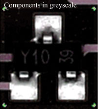
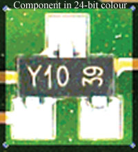
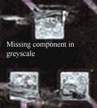
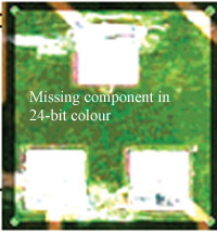
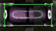
Among the common causes of false alarms are simple factors like board colour, board surface finish and the contrast between boards and components. Here, 24-bit colour can make a huge difference. Figure 1 illustrates examples of greyscale versus 24-bit colour for a simple SMT component and then a missing component.
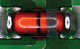
For verifying melf diodes for polarity, Figure 2 illustrates the poor contrast in greyscale that makes for difficult detection against the contrast and detection improvement available with full 24-bit colour.
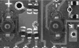
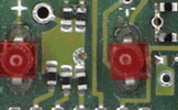
Another example of the advantage of colour image processing is shown in Figure 3 with the detection of coloured LEDs. Are those two LEDs red, green, amber, blue, clear or some other colour? Moving out of the grey world makes it clear that they are red.
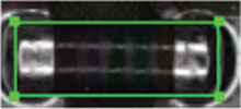
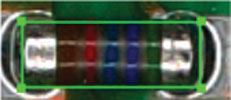
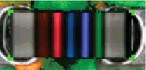
Again, looking at melf resistor values, greyscale imaging presents a difficult subject to discern (Figure 4a). 24-bit colour (Figure 4b) gives a different depth. These were imaged using normal lighting. Introducing additional technologies like coaxial lighting and data processing techniques such as synthetic imaging (Figure 4c) indicate just how much detection improvement can be gained when starting with 24-bit colour data.
Some of the practical examples shown above clearly illustrate how the depth of 24-bit processing can contribute significantly to the improvement of detection accuracy by helping to eliminate false defects. But what about getting to that point in the first place? Here again, true colour processing power provides a significant difference.
Traditionally, the bane of AOI has been the level of expertise and/or the amount of programming time that must be invested before the machine can even begin its inspection task. This means that truly useful new-product inspection programs often require too much programming time for today’s high-mix, quick-turn manufacturing environments. ‘Useful’ inspection programs optimise the balance between failing to detect true defects (known as escapes) while at the same time maintaining a low false defect rate.
Combining sophisticated device libraries for component identification with the import of pick-and-place program data for positional location is one example of the manner in which AOI machine programming can be accelerated. Achieving an optimal balance of true defects and false alarms quickly is the ultimate measure of fast programming. A system that is fast to program but which overlooks real defects (i.e. permits escapes) is just as useless as one that finds all defects and bombards operators with false alarms. In the latter case, operators will more and more quickly click through the many false alarms they are seeing and inevitably begin passing through real defects (operator escapes).
Modern AOI systems typically offer ongoing learning that can gradually weed out many false alarms, and indeed, 24-bit processing can dramatically accelerate that artificial intelligence process. But total reliance upon such an approach not only runs fundamentally against lean manufacturing principles, it is volume dependent and thus totally unsuitable for NPI and other high mix manufacturing situations where an effective AOI implementation can potentially deliver the most positive impact.
| Tel: | +27 11 609 1244 |
| Email: | [email protected] |
| www: | www.zetech.co.za |
| Articles: | More information and articles about ZETECH ONE |


© Technews Publishing (Pty) Ltd | All Rights Reserved
 printer friendly version