


The exponential growth of LED lighting has ushered in a vast selection of integrated circuit devices to provide controlled power to LEDs. No longer acceptable to an energy-conscious world, switched-mode LED drivers have long since replaced power-hungry linear current sources as the standard. Applications from flashlights to stadium scoreboards all require precise control of regulated currents.
In many instances, real-time changes in LED output intensity are required. This function is commonly referred to as dimming control. This article describes some basic LED theory and several techniques used to provide dimming control to switched-mode LED drivers.
LED brightness and colour temperature
LED brightness
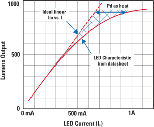
The concept of the brightness of visible light from an LED is fairly easy to understand. Assigning a numerical value to the perceived brightness of an LED’s output can simply be measured in units of luminous flux density, called candelas (cd). The total power output of an LED is a measurement of the amount of Lumens (lm). It is also important to understand that average forward LED current determines the brightness of an LED.
Figure 1 shows the relationship between forward LED current and Lumen output for a certain LED. The relationship is remarkably linear over useable ranges of IF (forward current). Note the nonlinearity appearing as IF increases. Reduced efficacy in Lumens per Watt arises as the operating current exceeds the linear range. Operation above the linear range results in output power converted to heat from the LED. This wasted heat burdens the LED driver and increases the complexity of the thermal design.
LED colour temperature
Colour temperature is a metric that describes the colour of the LED and is quantified in LED datasheets. The colour temperature of a given LED will be specified within a range and will shift with variances in forward current, junction temperature and age. Lower colour temperatures are more red-yellow (called warm) and higher-valued colour temperatures are more blue-green (called cooler).
Many coloured LEDs will specify dominant wavelength instead of colour temperature and are also subject to shift in wavelength.
LED dimming methods
Two popular methods for dimming LEDs in switched-mode driver circuits exist: pulse-width modulation (PWM) dimming and analog dimming. Both methods control the time-averaged current through the LED or LED string, but there are differences between the two which become evident when examining the advantages and disadvantages of the two types of dimming circuits.
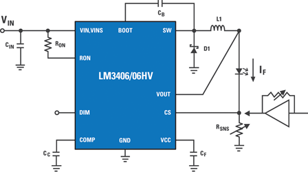
Figure 2 shows a switched-mode LED driver in a buck topology. VIN must always be higher than the voltage across the LED + RSNS. The inductor current is the LED current. The current is regulated by monitoring the voltage at the current sense or CS pin. As current sense or CS starts to fall below a set voltage, the duty cycle of the current pulses going through L1, the LED and RSNS increase, which increases the average LED current.
Analog dimming
Analog dimming of LEDs is the adjustment of cycle-by-cycle LED current. More simply put, it is the adjustment of the constant LED current level. Analog dimming can be accomplished by an adjustment of the current sense resistor RSNS, or by driving an analog voltage on some DIM function pin of the IC.
Analog dimming by adjustment of RSNS
It is clear from Figure 2 that a change in value of RSNS will correspond to a change in LED current with a fixed CS reference voltage. If one could find a potentiometer that could handle the high LED current and was also available in sub-1 Ω values, this would be a viable method to dim the LED.
Analog dimming by driving DC voltage on the CS pin
More complex is a technique to directly control the cycle-by-cycle current of the LED by means of driving a voltage into the CS pin. The voltage source is typically inserted into a feedback loop where LED current is sampled and buffered by the amplifier (Figure 2). The LED current can be controlled by the gain of the amplifier. With this feedback circuitry, functionality such as current and thermal foldback can be implemented for further LED protection.
A disadvantage to analog dimming is that the colour temperature of the emitted light can vary as a function of LED current. In situations where the colour of the LEDs is critical, or the particular LED exhibits a large change in colour temperature with changes in LED current, dimming the output of the LED by changing the LED current would be prohibitive.
PWM dimming
The PWM method of dimming is the actual start and restart of the LED current for short periods of time. The frequency of this start-restart cycle must be faster than the human eye can detect to avoid a flickering effect; about 200 Hz or faster is usually acceptable.
The dimming of the LED now becomes proportional to the duty cycle of the dimming waveform, governed by the formula:
IDIM-LED + DDIM x ILED
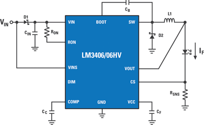
where IDIM-LED is the average LED current, DDIM is the duty cycle of the dim waveform, and ILED is the nominal LED current setup with the selection of RSNS as shown in Figure 3.
Modulating the LED driver
Many modern LED drivers feature a specialised PWM DIM pin that accepts a wide range of PWM frequencies and amplitudes, allowing a simple interface to external logic. The DIM function only shuts down the output drive while leaving the internal circuitry operating, avoiding the delay of restarting the IC. Output Enable pins and other logic shutdown functions can be used.
Two-wire PWM dimming
Two-wire PWM dimming is a popular method for automotive interior lighting. As VIN is modulated below 70% of VIN-NOMINAL, the VINS pin (Figure 3) detects the change in voltage and converts the PWM waveform into a corresponding PWM of the output drive. The disadvantage to this method is the power source to the converter must contain a circuit to provide a PWM waveform to its DC output.
Fast PWM dimming with a shunt device
Because of the delays in shutdown and startup of the converter’s output, there is a limit to the PWM dimming frequency and range of duty cycles. To help overcome this delay, an external shunt device such as the FET shown in Figure 4 can be placed parallel to the LED or LED string to quickly bypass the converter’s output current around the LED(s).
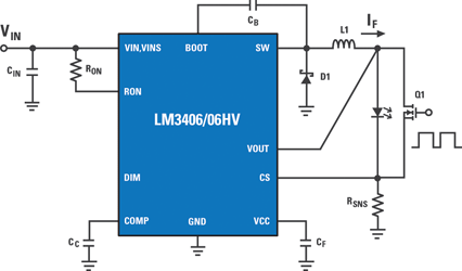
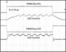
The current in the inductor stays continuous during the LED shutdown time, avoiding the long delay in ramping up and down the inductor current pedestal. The delay time now shifts to the limits of the shunt device’s rise and fall times. Figure 4 shows the LM3406 fitted with a shunt FET and a plot comparing the LED on/off delays between using the DIM function pin vs. the shunt FET. The output capacitance used in both of these measurements is 10 nF and the shunt FET is an Si3458.
Caution should be used when shunting the LED current with current-mode converters because of the overshoot in output current when the FET turns on. The LM340x family of LED drivers are controlled on-time converters and will not exhibit this overshoot. Output capacitance across the LEDs should be kept low to maximise on/off /on transition speed.
A disadvantage to the fast-dim circuit vs. shutting down the outputs is loss of efficiency. While the shunt device is on, a power dissipation of VSHUNT-DEVICE x ILED is lost as heat. Use of low RDS-ON FETs will minimise this loss of efficiency.
LM3409 multiple dimming functions
National Semiconductor’s LM3409 is an LED driver that provides functionality for easy analog and PWM dimming. There are four possible ways to implement LED dimming on this part:
1. Analog dim by directly driving the IADJ pin with a voltage source from 0 V to 1,24 V.
2. Analog dim by placing a potentiometer between IADJ pin and GND.
3. PWM dim with the Enable pin.
4. PWM dim by external shunt FETs.
The LM3409 is wired for analog dimming by use of a potentiometer (Figure 5). An Internal 5 μA current source creates a voltage across RADJ, which in turn varies the internal current sense threshold. The IADJ pin can be directly driven with a DC voltage for the same effect.
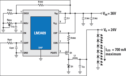
Figure 6 shows a plot of measured LED current vs. the potentiometer resistance between the IADJ pin and GND. The flat top at 1 A represents the maximum nominal LED current, set by the current sense resistor RSNS shown in Figure 4.
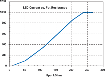
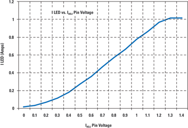
Figure 7 shows the measured LED current as a function of driven DC voltage onto the IADJ pin. Notice the same maximum LED current set by RSNS. Both analog dimming options are easy to implement and provide very linear dim levels down to around 10% of maximum.
Summary
There are many approaches to dimming LEDs powered by switched-mode regulators. The two main categories, PWM and analog, both have advantages and disadvantages. PWM dimming greatly reduces colour changes in the LED with varying brightness levels, at the expense of additional logic to create the PWM waveforms. Analog dimming can be a more simplistic circuit, but may be inappropriate for applications that require a constant colour temperature.
| Tel: | +27 11 923 9600 |
| Email: | [email protected] |
| www: | www.altronarrow.com |
| Articles: | More information and articles about Altron Arrow |


© Technews Publishing (Pty) Ltd | All Rights Reserved
 printer friendly version