


USB – Universal Serial Bus – is increasingly popular with embedded system designers as a general-purpose interface, especially for systems that must communicate with PCs or other computers. In part, that is because of the success of USB in living up to its promise of universality.
It was introduced in the mid-1990s with the intention of simplifying the assortment of interfaces, each with their own connectors, that had expanded on every PC; for example, RS232 serial and parallel ports. One measure of USB’s progress is that those connectors have disappeared from all laptops and from many desktop PCs: USB also has other characteristics of a successful standard: it has been repeatedly upgraded to handle speeds well in excess of its original definition, and it has found uses in applications far beyond its original task of connecting peripherals to a PC.
Many of the characteristics that have contributed to USB’s growth in the consumer space also make it attractive to the embedded system designer. For example, it offers ‘hot’ connection and disconnection, with full system support, of peripheral devices, and it provides (within defined limits) power to connected devices. The embedded designer may have to connect to a host or device that already has USB, so may have no choice but to use the standard. Even if that is not the case, the ready availability of hardware – from ICs through to connectors and cables – and software for a USB implementation increases its appeal. Many microcontrollers, such as Microchip’s PIC18F4550, integrate USB as one of the primary serial interfaces. USB’s robustness and flexibility does come at the cost of some complexity, and presents a range of choices that the designer must make.
USB fundamentals
USB is a four-wire bus, with two signal lines and two power connections: a fifth connection, added in the later OTG (on-the-go) extension of USB 2.0, is part of the support for dual-role devices that can function both as a limited-capability host and as a USB peripheral. In version 1.1 of the specification, data rates were defined as full speed, at 12 Mbps, or low speed, 1,5 Mbps. USB 2.0 added high speed, at 480 Mbps.
USB implements extensive backwards-compatibility with fall-back to the fastest rate that all devices in a connection can support; for example, a device can be USB 2.0-compliant – it will negotiate and interoperate with other USB 2.0 devices – without itself being high-speed-capable. As a packet-based bus, and depending on the mode of operation selected, USB has a significant and variable overhead on its transmission, so throughput is always less than the raw bit rate. USB 3.0, which will be seen on devices that will start to appear on the market soon, extends the data rate to 4,8 Gbps.
USB operates with a tiered-star architecture; devices plug into a host that manages the bus and provides power. A device can be a hub that provides multiple downstream connections (and can, if self-powered, provision power to those downstream devices) to expand the bus to a theoretical maximum of five levels of branching, and 127 devices in total. The USB protocol establishes virtual ‘pipes’ between host and endpoints in each device. The host automatically detects and discovers each new device that is inserted into a USB connection, and learns its properties through a process of enumeration; the device is required to pass a series of descriptors to the host.
Peripheral descriptors
Peripherals carry a series of descriptors that progressively provide the host with more and more information about the peripheral or about subsequent descriptors, in a hierarchy of information, until the host finally gains all the parameters it needs to communicate effectively with the device. There are four general descriptors that apply to all USB devices.
The device descriptor describes the most general information about a USB device. For instance, it passes to the host the product and vendor, tells it how many configurations the device has, and how many configuration descriptors the host must request. The configuration descriptor provides information about a specific device configuration; multiple configurations can exist for one device. The interface descriptor tells the host how many endpoints a device feature uses and also declares the Class identity of a device. The endpoint descriptor (one per endpoint) tells the host if an endpoint is an IN or OUT endpoint, and what the endpoint number is. Reference 1 is a series of technical notes that, using the example of a PC-market peripheral, provides an introduction to the structure and use of USB descriptors.
The USB standard defines and approves a number of device classes, each of which requires a class driver in the host software; some of the most commonly-encountered classes being human interface, mass storage and communication. The USB standard permits a custom, or vendor-specific, device class which will typically involve the designer in a deeper level of interaction with the detail of USB.
Data transfer types
USB defines four transfer types (see Table 1). Control sends short commands and queries to the device or receives status responses from the device, and every device must support the control transfer mechanism as a means of giving the host access to its descriptors. It is also the only mechanism for which the data format is completely pre-defined. Interrupt data transfers are designed for devices that send or receive data at a fixed interval. This mode guarantees latency and provides retry attempts in case of failure due to errors on the bus. Although the name suggests otherwise, Interrupt mode is not event-triggered. This mode of transfer is intended for devices where data is transferred at a fixed, predetermined rate.
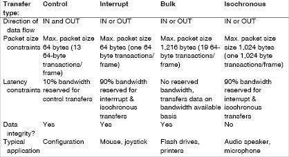
Bulk transfer mode is suitable for devices such as printers and storage devices, which need to transfer large amounts of data for which integrity is more important than timing. As time is not critical, this transfer mode has no dedicated bandwidth and transfers data as bandwidth becomes available. Isochronous mode provides real-time streaming data transfer without error detection, for data types such as streamed audio.
USB splits the available bandwidth into frames, which the host controller supervises. Each low- or full-speed frame contains 1,5 KBytes and starts every millisecond. In each frame, all devices using isochronous and interrupt data-transfer types get a slot, so that they are guaranteed the bandwidth and timing they require. Any additional space is allocated to bulk and control transfers. Although the maximum bit rate may be 1,5, 12 or 480 Mbps, any one device will see a fraction of the bandwidth. In fact, the bus may run out of bandwidth, depending on the number of USB devices connected to a host controller.
Adding security
Although the original conception of USB showed considerable foresight, and incorporated many features that would later be used to support advanced features, there is no native support for security. Clearly, applications that connected simple peripherals to a PC did not need to include protection, the data sent from a keyboard, or to a printer, being known. However, extending the reach of USB’s application brings it into areas where the data payload is not predetermined, and the lack of a built-in security or encryption mechanism may be a concern. This is especially true because USB analysers – hardware and software – are readily available, even free. Inspection of bus traffic and identification and extraction of the data payload is trivial.
The first step to creating a more secure USB custom application is to choose an encryption algorithm that fits the application’s needs. As always, the engineer needs to keep in mind that security is not absolute. Any level of added security has a cost, both monetary and in system overhead. It has often been said that the objective should be to apply just enough security to make the cost of breaking it greater than the value of the data that might be intercepted.
There are several algorithms to choose from that vary in the security they provide, their size, the time it takes to encrypt or decrypt a block of data, and their native support in various compilers. It should be noted that some countries apply export controls to algorithms with a certain key size: at defined levels of security they have the same status as munitions. Depending on the type of algorithm and the key size used, the application may need to be approved for export (Reference 2).
Encryption algorithm options
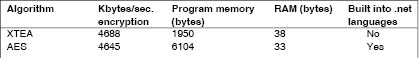
The Advanced Encryption Standard (AES) is a good choice, as it is fairly secure and can be applied at varying levels with differing key sizes. AES can be implemented with a small to moderate size of code (around 8 KBytes). For the level of security provided, AES is one of the better algorithms. Finally, AES is default supported in the .NET framework. The Data Encryption Standard (DES) and Triple Data Encryption Standard (TDES) are two alternative algorithms that are also supported by default in the .NET framework. They are slower, less secure and take up more code size than AES, but are still being used in many applications.
The second version of the Tiny Encryption Algorithm (XTEA) is also a potential candidate. It is not supported by default in the compiler tools, but it is very simple and very easy to implement. XTEA is one of the smallest algorithms available (see Table 2 and Reference 3) and is well suited for applications that need to fit in small memory spaces. As it has not yet been exhaustively tested its ultimate security level is not as clear, but indications are that it is relatively secure (Reference 4).
Once an algorithm is chosen, the next step is to consider any impacts that its block size will have on the application. Consider, for example, AES encryption with a block size of 16 Bytes. This means that the data sent by the application over the USB bus must be a multiple of 16 Bytes. If a data payload of less than 16 Bytes needs to be sent, then the data will need to be padded to meet the required block size. If padding is used to fill the rest of the data block, these Bytes must still be transmitted to the decrypting device and correctly discarded from the decrypted payload. Encryption algorithms are designed such that a single bit error or missing bit will prevent the data block from being decrypted.
Key exchange
A final point to consider is the generation and maintenance of the encryption keys. AES, TDES and XTEA, while being fast, small and secure, are symmetrical algorithms; that is, they use the same key at both ends of the data exchange. If the system is once cracked, it will always be cracked and will never require additional effort to crack a future transmission.
Asymmetrical algorithms take a large amount of firmware space to implement and are very slow compared to symmetric encryption algorithms; but they allow the exchange of information without a shared key. They are typically used to securely exchange a new uniquely generated symmetrical key for each connection.
Microchip Technology provides a free USB stack (Reference 5) that includes several custom-application style scenarios, as well as implementations of the AES, DES, XTEA and other encryption algorithms. The stack and libraries can be combined with a Microsoft Visual Studio C++ Express Edition compiler and its native support for the AES algorithm to create an example of an encrypted custom USB application.
The first steps to implementing basic encryption would be to add the AES encryption source code to the USB application, arrange for data padding to the appropriate block size, create a suitable key, and route data bound for the bus, or received from the bus, through the encryption algorithm.
Data on the bus, though encrypted, is still vulnerable to a number of attack strategies. Replay attacks take place when someone captures transmitted traffic and then, at a later point in time, replays the same data to convince the receiving system that the original stimulus or input data has been repeated. Counter strategies include adding random numbers to the data payload to produce a more random-looking behaviour of the communications traffic.
Attention may also need to be paid to the security of the PC or other system where the USB host resides. If the data sent over USB is decrypted on a PC, then at some point both the key and the raw decrypted data will reside in RAM, available for that application to read. A sophisticated attacker might write an application that scans the RAM on the PC, looking for potential keys or decrypted data.
References
Reference 1: Microchip Technology Technical Bulletin TB054, ‘An introduction to USB Descriptors;’ see also Bulletins TB055-TB058 at www.microchip.com
Reference 2: Commercial Encryption Export Controls, US Department of Commerce; www.bis.doc.gov/encryption/
Reference 3: Microchip Application Notes; AN953 ‘Data encryption routines for PIC18 MCUs,’ and AN1044 ‘Data encryption routines for PIC24 and dsPIC devices,’ at www.microchip.com
Reference 4: XTEA, Wikipedia entry; http://en.wikipedia.org/wiki/XTEA
Reference 5: The stack can be found at http://www.microchip.com/usb, and the corresponding data encryption libraries (part # SW300052) at www.microchip.com
| Email: | [email protected] |
| www: | |
| Articles: | More information and articles about Tempe Technologies |


© Technews Publishing (Pty) Ltd | All Rights Reserved
 printer friendly version