


Industrial electronic equipment commonly uses galvanic isolators to protect systems and users from potentially hazardous voltages.
It is well known that industrial equipment must operate reliably in the harshest environments, where strong electromagnetic fields, surges, fast transients and high noise floors are the norm. This environment presents challenges for designing reliable isolation circuits that deliver error-free operation over long equipment lifetimes.
Over the last four decades, optocouplers have been the ‘default’ signal isolation device, but recent breakthroughs in silicon isolation technology have spawned smaller, faster, more reliable and cost-effective solutions that have already begun supplanting optocouplers in many end applications. This article discusses industrial isolation issues and ways RF isolation technology can be applied to increase system robustness and performance.
RF isolator and optocoupler basics
Figure 1 shows top-level block diagrams of an optocoupler and Silicon Laboratories’ ISOpro isolator. As shown in Figure 1a, the optocoupler is a hybrid assembly having a light-emitting diode (LED) that emits light when forward biased, with brightness being proportional to LED forward current.
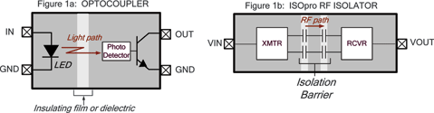
Emitted light passes through an optically transparent insulating film (or dielectric), striking a photodetector and causing a current flow that biases the output transistor on. When LED forward current no longer flows, light emission ceases and the output transistor turns off.
The basic operation of the ISOpro isolator is analogous to that of the optocoupler, except that an RF carrier is used instead of light (Figure 1b). The ISOpro isolator consists of two identical semiconductor dies connected together within a standard IC package forming an RF transmitter and receiver separated by a differential capacitive isolation barrier. Data is transferred from input to output using simple on/off keying (OOK). When VIN is high, the transmitter generates an RF carrier that propagates across the isolation barrier to the receiver. The receiver asserts logic 1 on VOUT when sufficient in-band carrier energy is detected. When VIN is low, the transmitter is disabled and no carrier is present. The receiver, therefore, detects no in-band carrier energy and drives VOUT low.
Unlike the optocoupler, each ISOpro channel occupies little die area, making possible cost-effective, high-channel-count isolators. Additionally, monolithic semiconductor process technology enables ISOpro technology to be combined with other semiconductor functions and processes to create highly integrated products with built-in isolation, such as isolated analog data converters and communication transceivers. These integration advantages enable a broader, more comprehensive ISOpro product roadmap than the optocoupler.
System considerations
Regardless of implementation, isolators must meet safety standards for robust galvanic isolation. They must also be reliable enough to outlast the equipment in which they are installed, which, in the industrial world, can mean decades of use.
Designers must ensure that isolation circuits can withstand electrical stresses that can cause physical damage and reject data-corrupting noise from any number of sources. Therefore, the designer must carefully consider key isolator operating parameters such as common-mode transient immunity, key timing parameters such as propagation delay and pulse width distortion, and field-related specifications such as EMI and RF susceptibility. Likewise, continuous working voltage and mean time to failure (MTTF) are important indicators of device service life.
High-voltage insulation reliability
Insulation reliability directly affects the isolator’s ability to safeguard against user exposure to high voltage and is of paramount importance. The insulator is the ‘heart’ of the isolation barrier and key to maintaining system safety. It is very important that the insulation be uniform, with no voids that can cause a localised breakdown. Insulator uniformity is a function of insulator material and the fabrication process.
The dielectric strength of the optocoupler’s injection-moulded plastic compound can vary by as much as 300% due to voids created during fabrication. In contrast, ISOpro isolators use semiconductor oxide layers for their primary insulator. The CMOS oxide deposition process is very tightly controlled and highly uniform, and the resulting variation in dielectric strength is only 20%. Each oxide layer has a breakdown voltage of 500 V a.c.RMS per micron. Higher voltages (eg, 5 kV a.c.RMS) are implemented by simply stacking oxide layers during wafer fabrication. The result is a higher absolute maximum breakdown voltage in a substantially smaller size compared to optocouplers and insulator reliability that is independent of the packaging process.
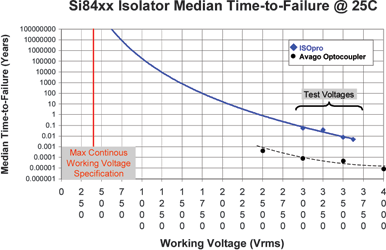
Figure 2 compares the MTTF of the ISOpro isolator versus an optocoupler. Both devices were measured on the same equipment and under the same conditions. As shown, the extrapolated MTTF for a 2,5 kV a.c.RMS, 6-channel ISOpro trends toward 1x10⁸ years at 25°C with 500 V d.c. applied.
Safety certifications
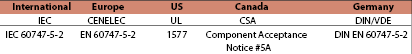
International safety standards provide test methodologies and guidelines to ensure end-equipment safety from electrical shock, mechanical hazard, and fire and electromagnetic interference. The component-level international safety standards for optocouplers and other isolators (including ISOpro isolators) are summarised geographically in Table 1.
Isolator classifications include ‘Basic’ and ‘Reinforced’. Basic isolation is intended to provide a single level of protection against electrical shock only and cannot be considered failsafe. While these devices are accessible to a user, they must be contained within the system. Basic isolation devices are 100% safety tested at 2,5 kV a.c.RMS for a period of 1 minute and, typically, have a minimum creepage of 3,2 mm. Reinforced isolation provides two levels of protection, making these devices failsafe and allowing user access. These devices are 100% safety tested at 5 kV a.c.RMS for a period of 1 minute and typically provide a minimum creepage of 6,4 mm.
Note that the exact creepage distance and rated isolation voltage requirements vary from one system to another according to the system’s specifications and targeted environmental operating conditions (pollution degree).
Certification testing involves subjecting the isolator component to various stresses as prescribed by test standards while monitoring the device under test for failures that could compromise safety.
Table 2 is an excerpt from the electrical strength test prescribed by IEC60950. The test voltages shown assume homogeneous joined package surfaces, such as moulding compound only. However, different materials are used in the isolation barrier of both optocouplers and the ISOpro isolators. For example, the ISOpro isolator barrier uses silicon dioxide as the primary insulator and plastic moulding compound as the secondary insulator.
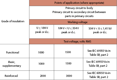
This type of non-homogenous, joined construction is referred to as ‘cement joint’ and requires the certification agency to proof test the isolator by increasing the test voltages of Table 2 by a factor of 1,6. For example, reinforced components that support a peak or DC working voltage of 354 V must tolerate a 4800 V a.c.RMS dielectric withstand potential for 1 minute to pass agency certification for a rated voltage of 4800 V a.c.RMS. In addition, the manufacturer’s production test for this isolator must include testing each component at 120% of its rated value for 1 second. Therefore, the 354 V isolator referenced above would be production tested for 1 second at 5760 V a.c.RMS to ensure its integrity.
This article will be continued in the next edition of Dataweek.
For more information contact Gary de Klerk, NuVision Electronics, +27 (0)11 894 8214, [email protected], www.nuvisionelec.co.za
| Tel: | +27 11 608 0144 |
| Fax: | +27 11 608 4723 |
| Email: | [email protected] |
| www: | www.nuvisionelec.com |
| Articles: | More information and articles about NuVision Electronics |


© Technews Publishing (Pty) Ltd | All Rights Reserved
 printer friendly version