


LED lighting products are becoming more and more prevalent. The market for these products is extensive; practically any traditional method of lighting can be replaced with a planet-friendly LED version. LEDs make an excellent domestic light source because of their long life and excellent energy efficiency.
Components for LED lighting design must be selected carefully to ensure that they meet the lifetime and energy efficiency requirements of the end products. These requirements can be demanding – LED lighting products may have an expected lifetime of more than 40 000 hours, for example. It is therefore crucial that all parts of the circuit are able to meet these requirements.
Ceramic capacitors in this type of circuit can be subject to high voltages and conditions unlike those usually seen in domestic appliance applications. These conditions can adversely affect the lifetime of ceramic capacitors which can mean they fail before the minimum lifetime of the end product is reached. This article explains the root of the problem and makes recommendations for ensuring ceramic capacitors do not cause lifetime problems for LED lighting products.
Typical conditions in LED circuitry
A typical LED lighting circuit is shown in Figure 1. For C1, C2 and C3, safety-recognised capacitors should be selected that are rated 250 Vrms a.c..
C6 is the snubber capacitor for the diode; parts rated to withstand 250 V to 630 V d.c. are needed and these can have X7R temperature characteristics. For C7, the snubber capacitor of the FET, a higher voltage rating of 630 V to 1 kV d.c. is necessary, and Murata recommends type U2J temperature-compensated capacitors. C8 is the smoothing capacitor for the secondary circuit, for which any part rated to 100 V should be sufficient.
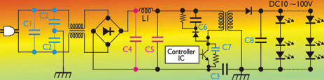
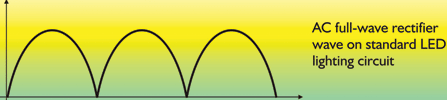
The capacitors in the circuit subject to the harshest conditions are C4 and C5, which act as AC smoothing or noise filter capacitors for the primary circuit. The typical working voltage on these capacitors is the full-wave rectified waveform shown in Figure 2. X7R capacitors that are rated to 250 V d.c. are often (wrongly) chosen for C4 and C5. The problem is that when high dielectric constant capacitors like these are subjected to full-wave rectified voltages, they succumb to the electrostrictive effect, which can cause fatal cracks in the dielectric material.
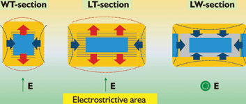
The electrostrictive effect applies to all dielectric materials. When an AC voltage is applied, the capacitor effectively stretches and shrinks in the different dimensions, as shown in Figure 3. Mechanical distortion and stress concentrate around the edge of the external electrode of the capacitor. If the AC voltage is large and the material has sufficient dielectric properties, after some time cracks can form under the external electrode which can lead to catastrophic short circuit failure of the component.
Mitigating the electrostrictive effect
There are a number of ways in which Murata mitigates the electrostrictive effect with specially-designed capacitor structure.
The first factor to take into account is the thickness of the dielectric material between the inner electrodes of the capacitor. This has a direct effect on the magnitude of the electrostrictive phenomenon. When constructing high-voltage capacitors, it is therefore essential to ensure the dielectric layer is thick enough to reduce the chip capacitor’s internal mechanical stress.
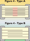
Secondly, the structure of the inner electrodes can contribute to the electrostrictive effect. Typical inner electrode structure is shown in Figure 4(b). By comparison, Figure 4(a) shows one of several types of Murata high-voltage capacitors. The centre area of this structure (marked red in the figure) is not active, and is therefore free from the effects of the electrostrictive phenomenon. This is one of several ways that Murata can protect its capacitors from internal mechanical stress.
Additionally, the thickness of the outer layer of the dielectric (the ‘dummy’ layer) can influence the formation of cracks. This layer is where cracks usually begin, so increasing its thickness, and thereby its mechanical strength, can help increase the lifetime of these products.
Last but not least, properties of the dielectric material itself can play a part, since it is only high dielectric constant materials that experience this effect. Murata carefully considers the properties of its materials to ensure that products specified for high voltage are constructed from suitable dielectric materials.
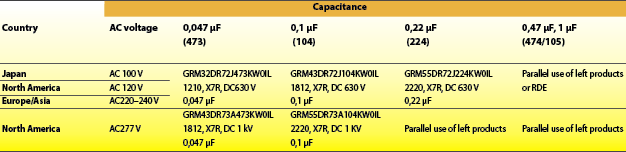
Taking all these factors into account, Murata recommends parts from its GRM series of multilayer ceramic capacitors for C4 and C5 that are able to exceed the minimum lifetime required whilst subjected to the operating conditions described above (see Table 1 for suggested part numbers). These parts have the X7R temperature characteristic and come in a range of values; 630 V d.c. rated parts come with capacitance between 0,001 and 0,22 μF and 1 kV d.c. rated parts range from 0,00047 to 0,1 μF.
Overall, the conditions experienced by ceramic capacitors in LED lighting circuits should not be underestimated. It is Murata’s experience that selecting the wrong capacitor can adversely affect the lifetime of the end product due to crack formation in the dielectric material of these capacitors. When designing this type of product, designers should take care to ensure they use adequately rated chip ceramic capacitors, with superior structure to mitigate the electrostrictive effect described above.
| Email: | [email protected] |
| www: | |
| Articles: | More information and articles about Tempe Technologies |


© Technews Publishing (Pty) Ltd | All Rights Reserved
 printer friendly version